14
Series 70 Electric Actuator
Operation and Maintenance Manual
SWITCH
COMMAND INPUT
4-20 mA DC 0-5 VDC * 0-10 VDC 2-10 VDC
1 Off On On On
2 Off Off On On
3
Off Off Off On
Output
4-20 mA DC 0-5 VDC 0-10 VDC 2-10 VDC
4 Off On On N/A
5 On Off Off N/A
6
Off On Off N/A
Forward Acting Reverse Acting
7 Off On
Fail in Last Position Fail Enable **
8 Off On
Fail Close Fail Open
9 Off On
Torque Torque
Switch Enable Switch Disable
10
Off On
*To control servo with a remote potentiometer, set the Command Input to 0-5VDC (see Command Signal
Connector section; page 8 Servo Pro Manual).
**Fail position is the position that the servo will travel to when the control signal is removed. It does not
apply to 0-5VDC or 0-10VDC Command Signals.
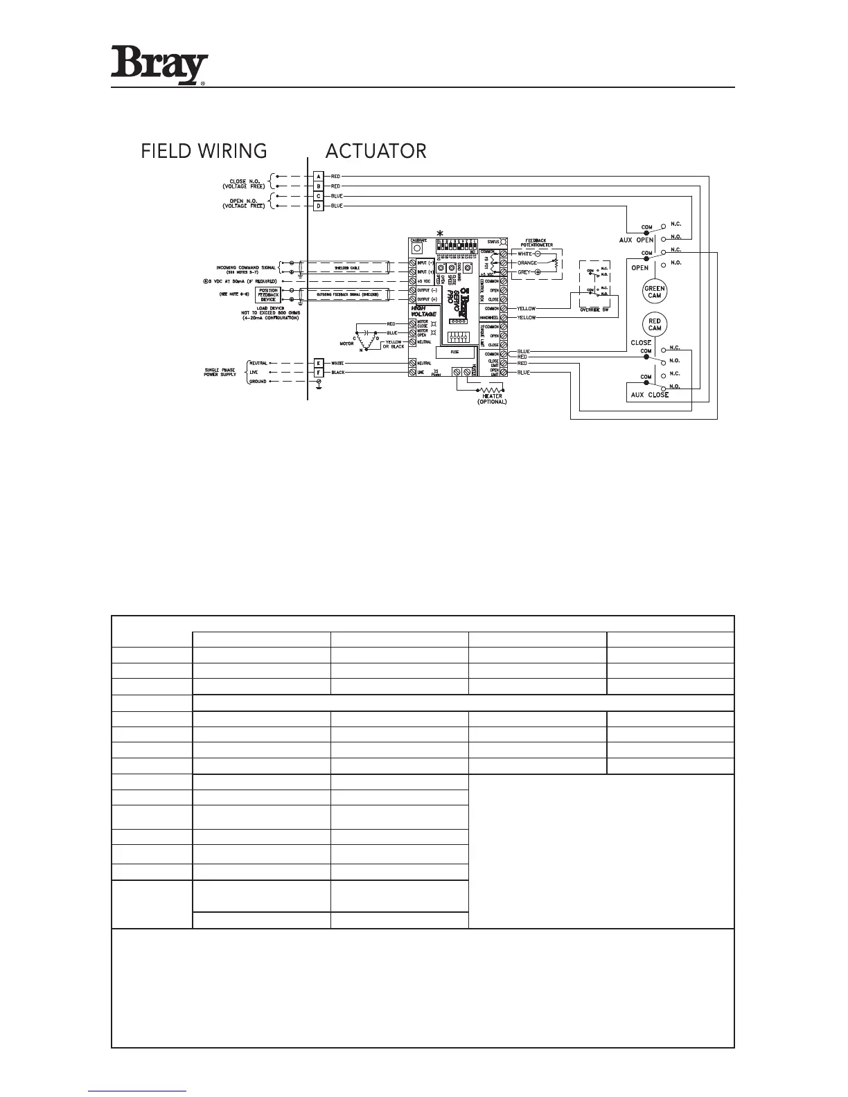
Typical Wiring Diagram: Modulating Service
Wiring diagram for unit with Form-C (SPDT) travel limit switches, “Voltage Free” Auxiliary open/close
switches, Servo and double override switches. (Drawn for actuator in its full closed position.)
Warning: Turn ALL Power Off prior to adjusting DIP switches.
 Loading...