10
Series 70 Electric Actuator
Operation and Maintenance Manual
Installation Procedure
• Disconnect all power to the unit.
• Remove the on/off duty, 9 point terminal strip and
its marker.
1. Disconnect all wiring to the terminal strip.
2. All wiring in the actuator is color coded to facilitate
wiring, and does not need to be tagged or marked.
3. Field wiring should be marked if it is not already
color coded.
Mount the servo module
4. Secure the servo card module onto switchplate with
the 2X #6 screws.
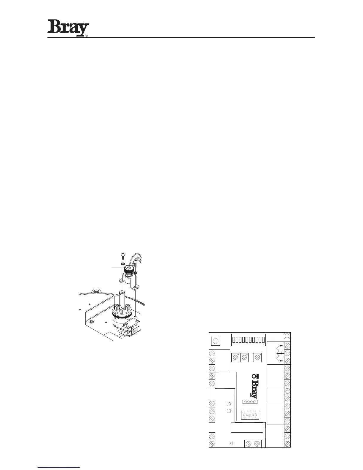
Install the potentiometer assembly
5. The potentiometer installs next to the camshaft
where there are two threaded holes provided.
6. The potentiometer assembly must be mounted in
the correct orientation, with the actuator in its fully
open (counter clockwise) position, the indicator shaft
should be in-line with raised green rib on pot gear.
7. Push the assembly towards the cam to mesh the pot
gears. Then tighten the mounting screws.
Note: On Housing Size 180, the raised green rib on
pot gear should be aligned with arrow on lower gear
box’s position indicator plate.
8.
Rotate the actuator handwheel so that the red cam
lobe is facing the body of the potentiometer. Make
sure that the cam is not touching the potentiometer
assembly. Readjust the assembly position if necessary.
Wire the potentiometer to the servo
9. Connect the potentiometer wires into the terminal
strip on the servo module.
10. Wire according to the wiring diagram provided.
Wire the servo to the actuator
11. Wire according to the wiring diagram provided.
12. See the servo calibration instructions.
Servo Calibration
The calibration procedure defines the limits of operation
of the Series 70 Actuator between the fully open valve
position and the fully closed valve position. The cams
on the Series 70 Actuator define the fully open and
closed positions of the valve and may be set at any
degree of opening. The only requirement is that the
open cam limit setting must set at a higher degree of
opening than the closed cam limit setting. In other
words, the “Open” position must be more open than
the “Closed” position.
Calibration is performed as follows:
1. Adjust the Open and Closed limit switch cams on
the Series 70 Actuator to the desired position.
2. Engage the handwheel and move the Series 70
Actuator to its mid position.
NOTE: An analog signal source is not required
for calibration. Press and hold the “Calibrate” Set
pushbutton for a minimum of 2 seconds. When the
servo status LED begins to flag rapidly, release the
button. The servo will now seek both travel limits and
record these values to its nonvolatile memory. Following
a successful calibration, the status LED will begin to
flash a slow single green flash. If the calibration is
unsuccessful, the status LED will alternately flash red
and green. If this occurs, make sure the cams and the
potentiometer are set correctly.
This completes the “Self Calibration” procedure.
After completing the calibration procedure, it is
good practice to apply the fully closed and fully open
Command Signals, and verify that the S70 Actuator
moves to the proper positions.
* Refer to Servo Pro Version 3.0 Operation and
Maintenance Manual for more details
MOTOR
OPEN
1
ON
MOTOR
CLOSE
FUSE
NEUTRAL
NEUTRAL
LINE
 Loading...