3
Series 70 Electric Actuator
Operation and Maintenance Manual
Introduction
The Bray Series 70 is a quarter turn electric actuator
with manual override for use on any quarter turn valve
requiring up to 18000 in.lb of torque. Operating speeds
vary between 6 to 110 seconds.
Principle of Operation
The Series 70 actuator is divided into two internal
sections; the power center below the switchplate,
and the control center above the switchplate. Below
the switchplate the capacitor and gearmotor with its
spur geartrain drive a non-backdriveable worm gear
output. The override mechanism for manual operation
is also housed here. Above the switchplate is where
user required, readily accessible components are placed.
The camshaft assembly, limit switches, terminal strips,
torque switches, heater, and servo are all placed here
for easy access. External to the unit are adjustable
mechanical travel stops, a large easy to read indicator,
the unique manual override handwheel and dual
conduit entry ports. The external coating is a high
quality polyester powder coat which has exceptional
UV as well as chemical resistance.
Electrical Operation
The motors used in the Bray Series 70 are either
permanent induction split capacitor design (single
phase AC power), SCI (Three Phase AC Power) or PM
(DC Power). Travel limit switches are mechanical form
(SPDT) with contacts rated at 10 amp (0.8 PF), 1/2 HP
125/250 VAC. In cases where the torque capacity of
the unit is exceeded to the point where the motor stalls
and overheats, a thermal protector switch built into the
motor windings will automatically disconnect the motor
power. Once the motor cools sufficiently the thermal
protector switch will reset. Optional torque switches are
available in all units to prevent the possibility of stalling
the motor, thus reducing the necessity for an inoperable
thermal cooldown period. Torque switches installed by
Bray are factory adjusted to the output torque rating
of the unit using electronic torque testing equipment.
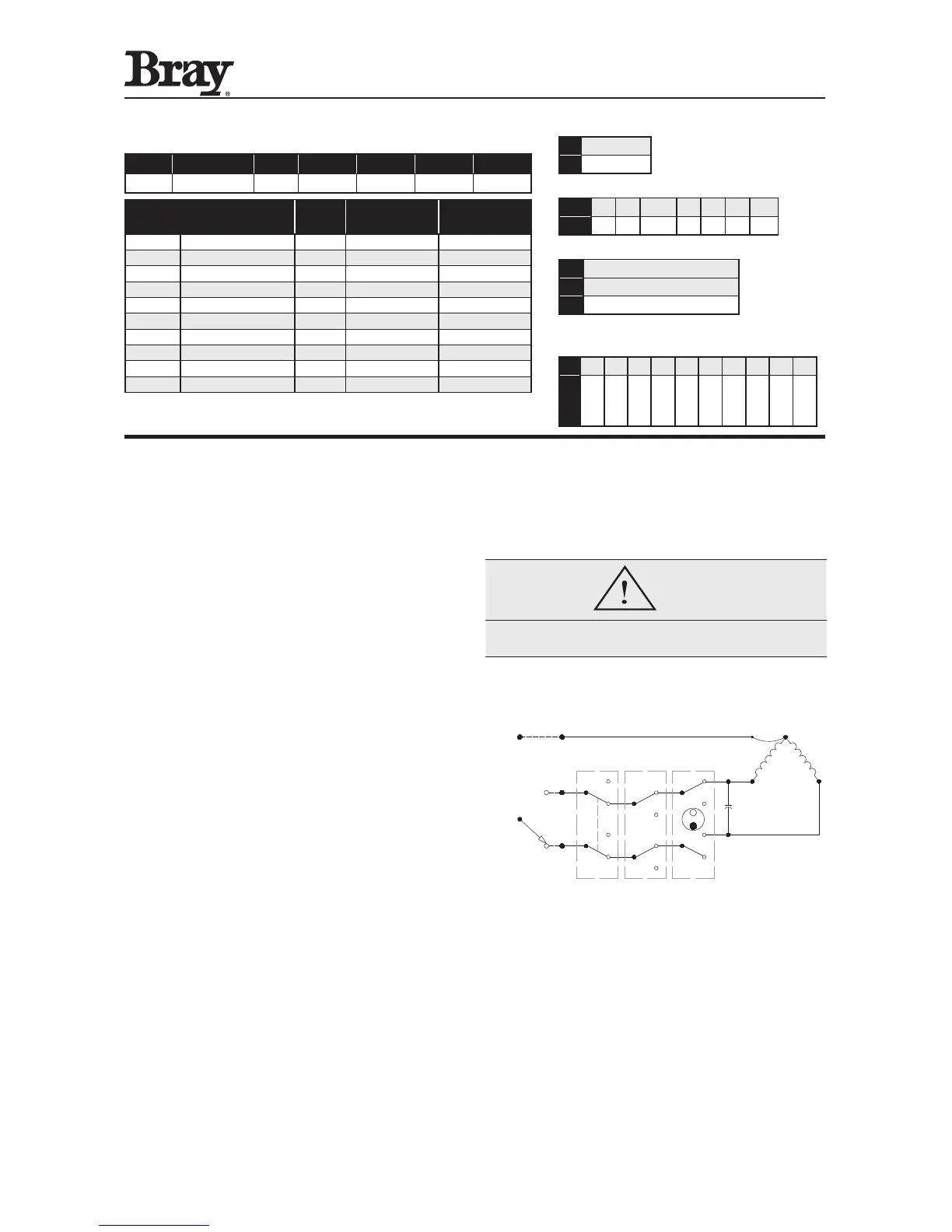
COM
N.C.
N.O.
CAMS
MOTOR
COM
N.C.
N.O.
COM
N.C.
N.O.
COM
N.C.
N.O.
COM
N.C.
N.O.
COM
N.C.
N.O.
1
2
3
NOTE: this is only a reference. For the actual wiring diagram refer
to the diagram placed inside the actuator cover.
Mechanical Operation
Mechanically, the ratio of the gearmotor determines the
speed of the unit. The gearmotor utilizes high efficiency
spur gears with various ratios for the different speeds.
Initial gear reduction through the spur gears is then
transferred to the worm shaft. The final gear reduction
and output is through a non-backdriveable worm gear
set. Positioning is determined by an indicator-cam
shaft linked to the output shaft. In the declutchable
condition the manual override drives the worm shaft
when engaged.
Part Numbering System Reference Chart
SerieS Torque Code Speed produCT STyle VolTage Trim
70 AAA X 113 Y Z 536
HouSing
S
ize
parT number
Torque
(In.Lbs)
Speed, ¼ Turn
(Seconds)
Supply
(Z Voltage)
6 70-003X-113YZ-536 300 30/15 0/2/4
6 70-006X-113YZ-536 600 30 0/3/4
12 70-008X-113YZ-536 800 30/15/6 0/4/8
12 70-012X-113YZ-536 1200 30/15/6 0/4/9
12 70-020X-113YZ-536 2000 30/15 0/2/3/4/5/6/7/8
30 70-030X-113YZ-536 3000 30/18 0/2/4/5/6/7/8
30 70-050X-113YZ-536 5000 30/18 0/2/3/4/5/6/7/8
30 70-065X-113YZ-536 6500 30 0/2/4/5/6/7/8
180 70-13WX-113YZ-536 13000 110 0/4
180 70-18WX-113YZ-536 18000 110 0/4
Use this chart as a guide to interpret the S70 electric actuator part number.
Note: Not all combinations are possible.
W - DESIGNATES THE OUTPUT BORE DIAMETER
0 2.5 Inches
1 1.97 Inches
X - DESIGNATES THE SPEED
X: 0 1 2 3 4 5 6
Sec: 60 30 15/18 10 6 8 110
Y - DESIGNATES STYLE
A Basic Unit - Declutchable
C 24VAC Unit with 24VAC Servo
D With Interposing Relay Board*
*Only available for 120VAC or 220VAC On/Off units
Z - DESIGNATES THE VOLTAGE
Z:
0 1 2 3 4 5 6 7 8 9
Voltage:
120VAC
12VDC
24VDC
24VAC
220VAC
380V
3-PH
400V
3-PH
440V
3-PH
480V
3-PH
208V
3-PH
 Loading...