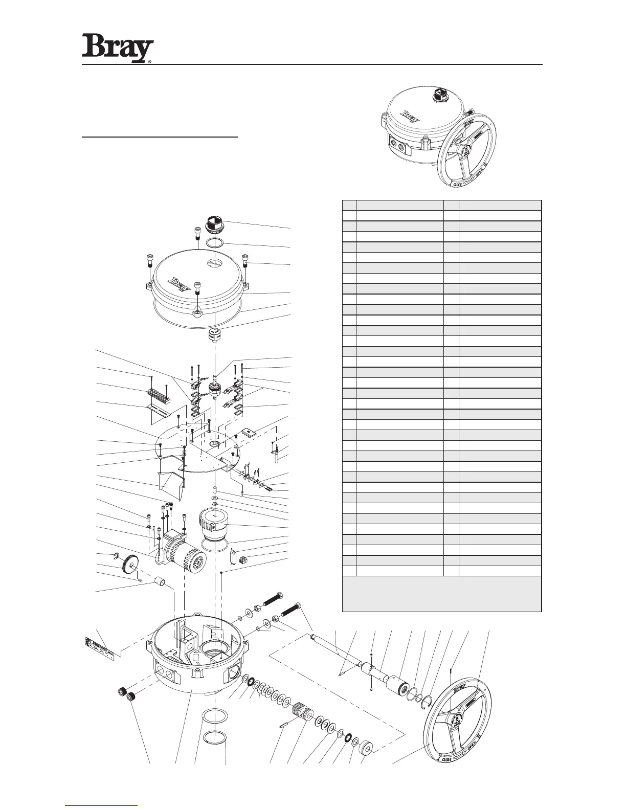
1 Position Indicator Cover 37 O-Ring
2 Position Indicator Seal 38 O-Ring
3 Cover Fastening Screw 39 Retaining Ring, Internal
4 Cover 40 Spring Pin
5 O-Ring 41 Handwheel Warning Label
6 Indicator Rotor 42 Handwheel
7 Cam Assembly 43 Manual Override Bushing
8 Switch Mounting Screw 44 Thrust Washer
9 Fiber Washer 45 Thrust Roller Bearing
10 Limit Open/Close Switches 46 Thrust Washer
11 Switch Spacer 47 Disc Spring
12 Torque Switch Cover 48 Worm
13 Pan Head Screw 49 Worm Gear Roll Pin
14 Heater Mounting Bracket 50 Retaining Ring, Ext.
15 Heater 51 Thrust Washer
16 Override Switch (SPDT Form C) 52 Base
17 Insulator 53 Conduit Entry Plug
18 Screw, Pan Head 54 Name Tag
19 Override Switch Trigger Pin 55 Bushing
20 Bushing 56 Drive Gear Key
21 Thrust Washer 57 Drive Gear
22 Retaining Ring 58 Retaining Ring, Bowed E-Ring
23 Worm Segment With Pads 59 Motor Assembly
24 O-Ring 60 Lock Washer
25 Capacitor 61 Dowel Pin
26 Terminal Strip 62 Socket Head Cap Screw
27 Override Spring Pin 63 Socket Head Shoulder Screw
28 O-Ring 64 Wire Entry Guard
29 Nylon Flat Washer 65 Washer, Ground Terminal
30 Lock Nut 66 Ground Screw
31 Travel Stop Bolt 67 Flat Head Screw
32 Worm Shaft 68 Switch Plate
33 Override Drive Pin 69 Terminal Strip Tag: 1-9
34 Spring Plunger 70 Terminal Strip
35 Manual Override Shaft 71 Pan Head Screw
36 Manual Override Sleeve 72 Aux Open/Close Switches
• Item 72 is optional.
• Items 13, 14, and 15 are optional.
• Item 12 is installed in units when torque switches are not
required.
 Loading...