1
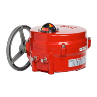
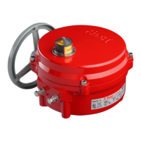
Series 70 Electric Actuator
Operation and Maintenance Manual
FOR MORE INFORMATION ON THIS PRODUCT AND OTHER BRAY PRODUCTS
PLEASE VISIT OUR WEBSITE – www.bray.com
Table of Contents
Safety Instructions - Definition of Terms . . . . . . . . . . . . . . . . . . . . . . . . . . . . . . . .2
Hazard-Free Use. . . . . . . . . . . . . . . . . . . . . . . . . . . . . . . . . . . . . . . . . . . .2
Qualified Personnel . . . . . . . . . . . . . . . . . . . . . . . . . . . . . . . . . . . . . . . . . .2
Part Numbering System Reference Chart . . . . . . . . . . . . . . . . . . . . . . . . . . . . . . .3
Introduction. . . . . . . . . . . . . . . . . . . . . . . . . . . . . . . . . . . . . . . . . . . . . .3
Principle of Operation . . . . . . . . . . . . . . . . . . . . . . . . . . . . . . . . . . . . . . .3
Electrical Operation. . . . . . . . . . . . . . . . . . . . . . . . . . . . . . . . . . . . . . . . .3
General Electrical Schematic . . . . . . . . . . . . . . . . . . . . . . . . . . . . . . . . . . . .3
Mechanical Operation . . . . . . . . . . . . . . . . . . . . . . . . . . . . . . . . . . . . . . .3
Manual Override Operation (Declutchable) . . . . . . . . . . . . . . . . . . . . . . . . . . . . .4
Pre-Installation Storage . . . . . . . . . . . . . . . . . . . . . . . . . . . . . . . . . . . . . . .4
Installation . . . . . . . . . . . . . . . . . . . . . . . . . . . . . . . . . . . . . . . . . . . . . .4
Mounting to a Valve . . . . . . . . . . . . . . . . . . . . . . . . . . . . . . . . . . . . . . . .4
Field Wiring . . . . . . . . . . . . . . . . . . . . . . . . . . . . . . . . . . . . . . . . . . . .4
Multiple Actuator (Parallel) Wiring . . . . . . . . . . . . . . . . . . . . . . . . . . . . . . . . .5
Actuator Diagram without I.R.B. . . . . . . . . . . . . . . . . . . . . . . . . . . . . . . . . . .5
Travel Limit Switch and Mechanical Travel Stop Adjustment. . . . . . . . . . . . . . . . . . . . .5
S70 On/Off Actuator with Interposing Relay Board (I.R.B.) . . . . . . . . . . . . . . . . . . . . .5
Close Travel Switch Adjustment . . . . . . . . . . . . . . . . . . . . . . . . . . . . . . . . . .6
Open Travel Switch Adjustment . . . . . . . . . . . . . . . . . . . . . . . . . . . . . . . . . .6
Disassembly and Assembly . . . . . . . . . . . . . . . . . . . . . . . . . . . . . . . . . . . . . .7
Procedure . . . . . . . . . . . . . . . . . . . . . . . . . . . . . . . . . . . . . . . . . . . . .7
Field or Factory Installable Options . . . . . . . . . . . . . . . . . . . . . . . . . . . . . . . . . .8
Torque Switches . . . . . . . . . . . . . . . . . . . . . . . . . . . . . . . . . . . . . . . . . .8
Torque Switch Mechanism . . . . . . . . . . . . . . . . . . . . . . . . . . . . . . . . . . . . .8
Heater . . . . . . . . . . . . . . . . . . . . . . . . . . . . . . . . . . . . . . . . . . . . . . .9
Installation Procedure . . . . . . . . . . . . . . . . . . . . . . . . . . . . . . . . . . . . . .9
Servo-Pro Module . . . . . . . . . . . . . . . . . . . . . . . . . . . . . . . . . . . . . . . . .9
Installation Procedure . . . . . . . . . . . . . . . . . . . . . . . . . . . . . . . . . . . . . 10
Servo Calibration . . . . . . . . . . . . . . . . . . . . . . . . . . . . . . . . . . . . . . . 10
External Signal Feedback Potentiometer . . . . . . . . . . . . . . . . . . . . . . . . . . . . . 11
Installation Procedure . . . . . . . . . . . . . . . . . . . . . . . . . . . . . . . . . . . . . 11
Set the Potentiometer . . . . . . . . . . . . . . . . . . . . . . . . . . . . . . . . . . . . . 11
Auxiliary Switches . . . . . . . . . . . . . . . . . . . . . . . . . . . . . . . . . . . . . . . . 11
Installation Procedure . . . . . . . . . . . . . . . . . . . . . . . . . . . . . . . . . . . . . 11
Auxiliary Switch Configuration Chart . . . . . . . . . . . . . . . . . . . . . . . . . . . . . . .12
Typical Wiring Diagram: On/Off Service . . . . . . . . . . . . . . . . . . . . . . . . . . . . . .13
Typical Wiring Diagram: Modulating Service . . . . . . . . . . . . . . . . . . . . . . . . . . . 14
Adjustments, Calibration and Status LED of Servo Pro . . . . . . . . . . . . . . . . . . . . . . 15
Status LED . . . . . . . . . . . . . . . . . . . . . . . . . . . . . . . . . . . . . . . . . . . . 15
Receptacles (Quick Connectors) . . . . . . . . . . . . . . . . . . . . . . . . . . . . . . . . . 16
Spinner. . . . . . . . . . . . . . . . . . . . . . . . . . . . . . . . . . . . . . . . . . . . . .17
Local Control Station (Single Phase Powered Actuators) . . . . . . . . . . . . . . . . . . . . . 17
Appendix A . . . . . . . . . . . . . . . . . . . . . . . . . . . . . . . . . . . . . . . . . . . . . 18
Basic Tools . . . . . . . . . . . . . . . . . . . . . . . . . . . . . . . . . . . . . . . . . . . . 18
Appendix B . . . . . . . . . . . . . . . . . . . . . . . . . . . . . . . . . . . . . . . . . . . . . 19
Actuator Troubleshooting Chart . . . . . . . . . . . . . . . . . . . . . . . . . . . . . . . . . 19
S70 Servo Pro Troubleshooting Chart . . . . . . . . . . . . . . . . . . . . . . . . . . . . . . 20
Appendix C - Exploded Views . . . . . . . . . . . . . . . . . . . . . . . . . . . . . . . . . . . .21
Series 70 - Housing Size 6 . . . . . . . . . . . . . . . . . . . . . . . . . . . . . . . . . . . . 21
Series 70 - Housing Size 12. . . . . . . . . . . . . . . . . . . . . . . . . . . . . . . . . . . .22
Series 70 - Housing Size 30. . . . . . . . . . . . . . . . . . . . . . . . . . . . . . . . . . . .23
Series 70 - Housing Size 180 for 3:1 Gear Box . . . . . . . . . . . . . . . . . . . . . . . . . . 24
Series 70 - 3:1 Gear Box . . . . . . . . . . . . . . . . . . . . . . . . . . . . . . . . . . . . . 25
 Loading...