5
Installation
COMBUSTION AIR SUPPLY
For a mobile home installation, the stove must be
connected to an outside source of combustion air. A
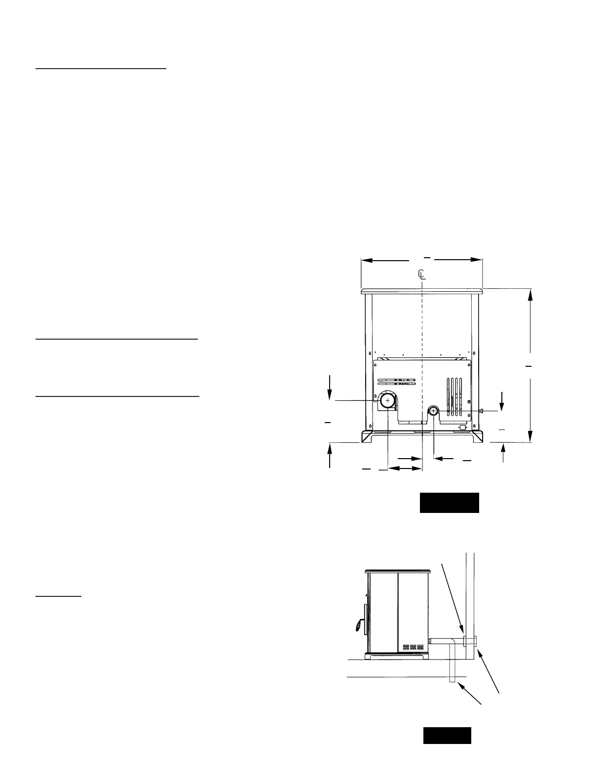
2” inside diameter metallic pipe, either exible or rigid,
may be attached to the inlet at the stove’s rear (refer
to gure 3). A rodent guard (minimum 1/4” wire mesh)
wind hood must be used at the terminus (refer to gure
4). All connections must be secured and airtight by
either using the appropriately sized hose clamp and/or
UL-181-AP foil tape.
For mobile home installations only: 2” inside diameter
pipe may be used for the rst 5 feet of combustion air
supply run. From 5 to 10 feet, use 2 3/4” inside diameter
pipe. No combustion air supply may exceed 10 feet.
Sources of Outside Combustion Air
a. In replaces
• Chimney top.
• Ash clean out door.
b. For freestanding installations
• A hole in oor near stove rear terminating only
a ventilated crawl space.
• A hole in the wall behind the stove.
WHEN OUTSIDE AIR IS NOT USED
If outside air is not used, it is important that combustion
air is easily available to the air inlet. A closeable outside
air register can be used in tightly insulated homes.
IMPORTANCE OF PROPER DRAFT
Draft is the force which moves air from the appliance
up through the chimney. The amount of draft in your
chimney depends on the length of the chimney, local
geography, nearby obstructions and other factors. Too
much draft may cause excessive temperatures in the
appliance. Inadequate draft may cause backpufng
into the room and ‘plugging’ of the chimney.
Inadequate draft will cause the appliance to leak
smoke into the room through appliance and chimney
connector joints.
An uncontrollable burn or excessive temperature
indicates excessive draft.
Take into account the chimney’s location to insure it
is not too close to neighbors or in a valley which may
cause unhealthy or nuisance conditions.
VENTING
This unit is certied for use with listed TYPE L-Vent,
3” or 4” diameter in size. The stove was tested with
Simpson Duravent brand. CLass “A” chimney is not
required. Refer to the instructions provided by the vent
manufacturer, especially when passing through a wall,
ceiling or roof.
This is a pressurized exhaust system. All vent connector
joints must be sealed with 500oF (260oC) RTV silicone
sealant to ensure consistent performance and avoid
smoke spillage. All horizontal connector joints must
be sealed with UL-181-AP foil tape. All vertical vent
connector joints are required to be secured with a
minimum of 3 screws.
DO NOT CONNECT THIS UNIT TO A CHIMNEY FLUE
SERVING ANOTHER APPLIANCE.
DO NOT INSTALL A FLUE DAMPER IN THE EXHAUST
VENTING SYSTEM OF THIS UNIT.
INSTALL VENT AT CLEARANCES SPECIFIED BY THE VENT
MANUFACTURER.
The chimney connector shall not pass through an
attic or roof space, closet or similar concealed space,
or a oor, or ceiling. Where passage though a wall, or
partition of combustible construction is desired, the
installation shall conform to CAN/CSA-B365, Installation
Code for Solid-Fuel-Burning Appliances and Equipment
FIGURE 3
25
3
4
“
32
5
8
“
6
5
8
“
8
7
8
“
7
5
16
“
2
7
16
“
TRIM
COLLAR
VENTILATED
CRAWL SPACE
RODENT
GUARD
FIGURE 4
25
3
4
“
32
5
8
“
6
5
8
“
8
7
8
“
7
5
16
“
2
7
16
“
TRIM
COLLAR
VENTILATED
CRAWL SPACE
RODENT
GUARD