8
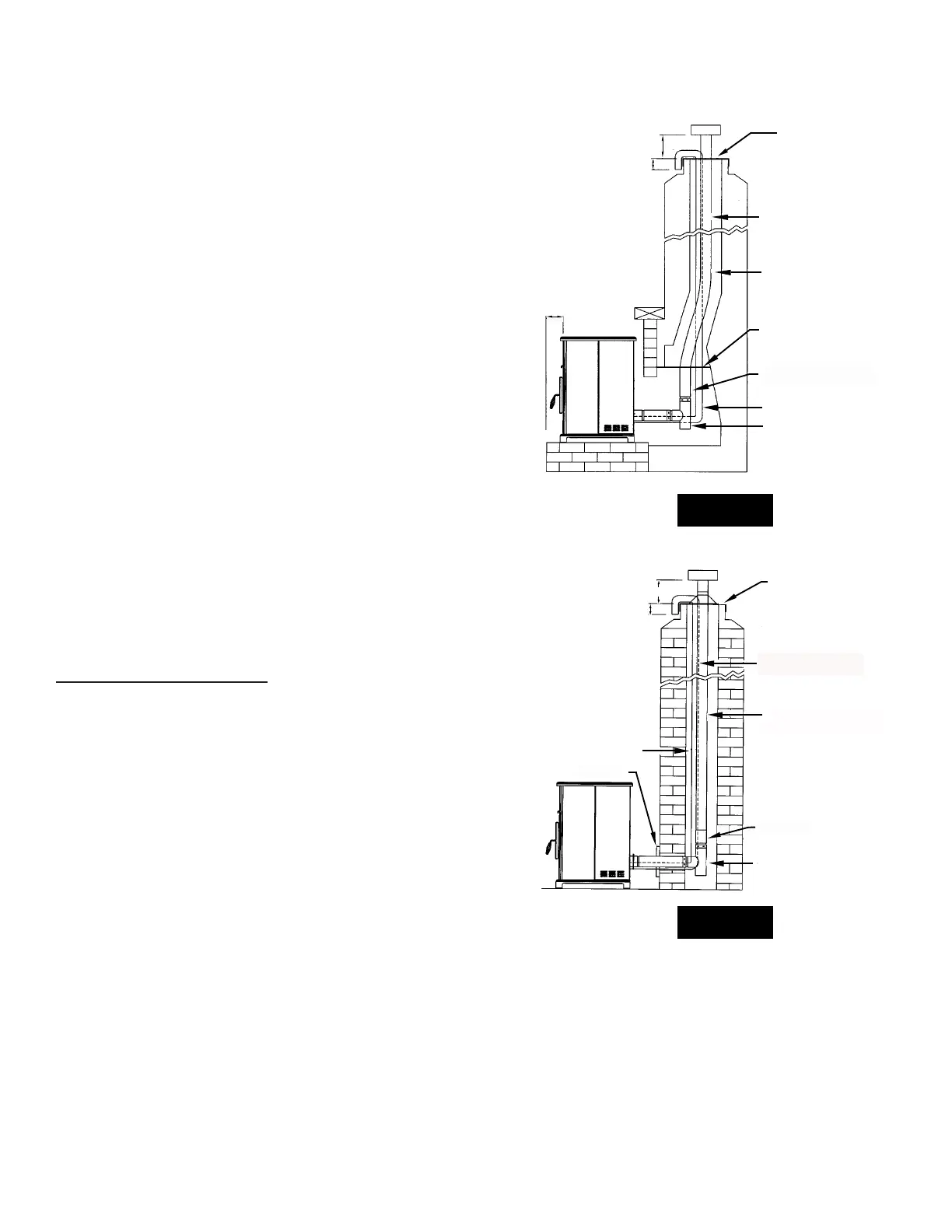
E. INSTALLATION THROUGH SIDE OF MASONRY CHIMNEY
NOTE: Follow L-Vent chimney manufacturer’s instructions.
1. Position the stove, adhering to the clearances in Figure
1. Mark the center of the hole where the pipe is to pierce
the masonry chimney.
2. It will be necessary to break out the masonry around the
location of the pipe center mark. Use a 4-inch diameter
hole for 3-inch pipe and 5-inch diameter hole for 4-inch
pipe.
3. Measure and build chimney top plate. Cut out holes for
chimney pipe, and if used, the outside air pipe.
4. Install the tee on the bottom of the vertical pipe system
and lower it down the chimney until the center branch
of the tee is level with the center of the hole in the
masonry, as shown in Figure 10.
5. Install and seal the top plate from Step 3 with non-
hardening mastic. Slip the storm collar over the pipe,
and while holding the pipe at the proper elevation, afx
the collar with a minimum of 3 1/4” stainless steel sheet
metal screws. Seal all joints and seams around the collar.
6. Connect the horizontal pipe by pushing it through the
hole in the masonry and lining it up with the branch in
the tee. Push the pipe into the tee while twisting it to
lock it into the tee.
7. If desired, once the horizontal pipe is in place, the space
between the pipe and masonry may be lled with high-
temperature grout.
8. Install the trim collar. An adjustable pipe length and
adapter may be needed to nish the connection to the
stove.
ELECTRICAL INSTALLATION
This stove is provided with a 6-foot grounded electrical cord
extending from the rear of the stove.
We recommend connecting to a good quality surge
protector that is plugged into a standard three-prong, 120V,
60Hz electrical outlet.
DO NOT connect the unit to a GFCI socket.
Voltage variations can lead to serious performance
problems. The Breckwell electrical system is designed for
120V AC with no more than 5% variation. Breckwell cannot
accept responsibility for poor performance or damage due
to inadequate voltage. If connected to an older, two-prong
outlet, a separate ground wire should be run to a proper
ground (refer this to a qualied technician). Always route the
electrical cord so that it will not come in contact with any
hot part of the stove.
FIGURE 9
FIGURE 10
6”
3”
TOP PLATE
(SEAL TO CHIMNEY TOP
WITH NON-HARDENING
MASTIC)
NOTE:
FOLLOW METAL
CHIMNEY INSTALLATION
INSTRUCTIONS
EXTENSION TO CHIMNEY TOP
REQUIRED.
3 OR 4 INCH STAINLESS STEEL
SINGLE WALL PIPE OR FLEX PIPE.
6”
BLANKING PLATE (SEAL WITH
NON-HARDENING MASTIC).
3 OR 4 INCH STAINLESS STEEL
FLEX PIPE.
OPTIONAL OUTSIDE AIR
CLEAN-OUT-TEE (TYPE L)
OR 90 DEGREE ELBOW
HEARTH
TOP PLATE
(SEAL TO CHIMNEY TOP
WITH NON-HARDENING
MASTIC)
6”
3”
NOTE:
FOLLOW METAL
CHIMNEY INSTALLATION
INSTRUCTIONS
EXTENSION TO CHIMNEY TOP
REQUIRED.
L-VENT OR OPTIONAL
3 OR 4 INCH STAINLESS STEEL
SINGLE WALL PIPE OR FLEX PIPE.
OPTIONAL OUTSIDE AIR
TRIM COLLAR
PIPE ADAPTER
CLEAN-OUT TEE (TYPE L)
Installation