Brent 1082/882 — Maintenance
4-5
Auger System (continued)
Lower Auger Assembly
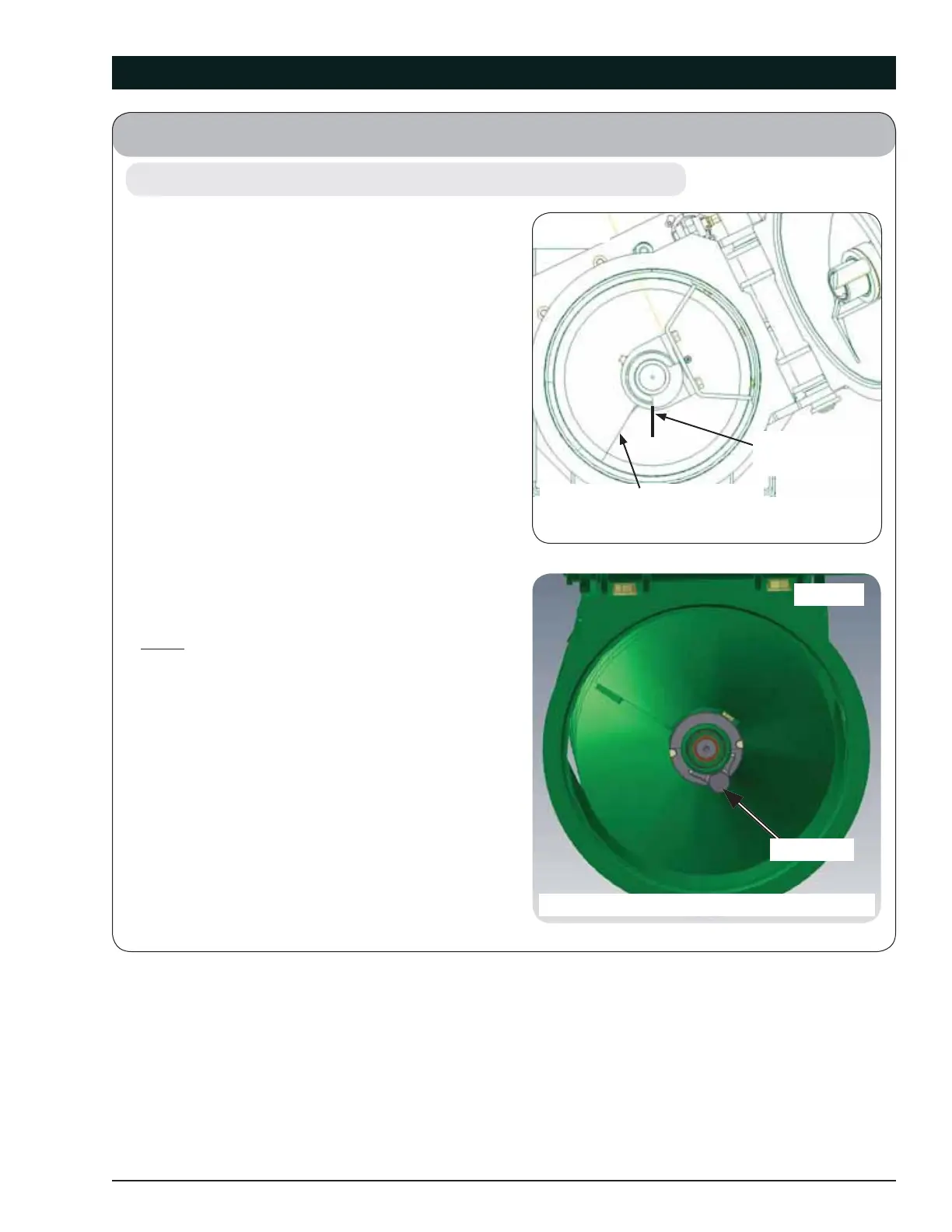
1. When installing the coupler into the auger pipe,
the lower auger fl ighting should be set with the
driving surface of the drive lobe at a 6 o’clock
position and the fl ighting edge at a 7 o’clock
position when looking from the top down to-
wards the gearbox, see fi gure 4-2. The upper
auger fl ighting should be set with the drive pin
at a 5 o’clock position and the end fl ighting will
be at an approximate 10 o’clock position when
looking at the picture frame of the upper auger,
see fi gure 4-3.
Lower Auger: Assemble the drive dog weld-
ment (281506B) and hanger bearing weldment
(281502B) to the auger making sure the drive
dog weldment contact surface (for upper au-
ger pin) is located approximately 30 degrees
behind the lower auger fl ighting trailing edge.
Secure with two 5/8-11UNC x 6 capscrews
(9390-136), lock washers (9404-029) and hex
nuts 5/8-11UNC (9394-014), installed opposite
of each other, as shown in Fig. 4-1.
NOTE: Position of the drive dog weldment
maintains correct timing and effi ciencies of the
upper and lower auger fl ightings.
2. Using a safe lifting device rated for a minimum
of 700 lbs., install the lower auger sub-assem-
bly into the lower auger housing. Align auger
end with the three pin drive bushing and se-
curely engage together. Secure hanger bearing
to housing wall with three 3/8-16UNC x 1 1/4
capscrews (9390-056), six fl at washers (9405-
076), three lock washers (9404-021) and hex
nuts 3/8-16UNC (9394-006) (Fig. 4-1).
3. Once secure, tighten hanger bearing weldment
hardware.
(May 2015)
FLIGHTING TRAILING EDGE
DRIVE LOBE
AT 6 O’CLOCK
LOOKING DOWN INTO THE LOWER AUGER FLIGHTING
Fig. 4-2
DRIVE PIN
Fig. 4-3
LOOKING UP INTO THE UPPER AUGER FLIGHTING
 Loading...