Model 428 User’s Manual OPERATION
Bristol Instruments, Inc. 10
Optical Signal Input
Never inspect or clean a fiber-optic cable without first disconnecting the entire
cable assembly from the optical source. Failure to take this precaution can
permanently damage your eyesight.
Use care in handling fiber-optic connectors. Always clean the fiber end prior to insertion
into the instrument’s fiber-optic connector for optimum performance. Failure to do so can
result in damage to the instrument. To prolong instrument service life, it is advantageous
to attach a new fiber-optic patchcord to the instrument and use its other end for the
connect/disconnect procedure.
Maximum safe input is 65 mW of optical power. Laser input power in excess of 65 mW
can result in damage to the instrument.
The optical signal under test enters the 428 system through an FC/UPC or FC/APC fiber-
optic connector on the front panel of the instrument (Figure 3.1).
1 Ensure that all fiber-optic connectors are clean and dry.
2 Connect your fiber-optic patchcord to the pre-aligned FC/UPC or FC/APC fiber-
optic connector on the instrument’s front panel. Make certain that the alignment
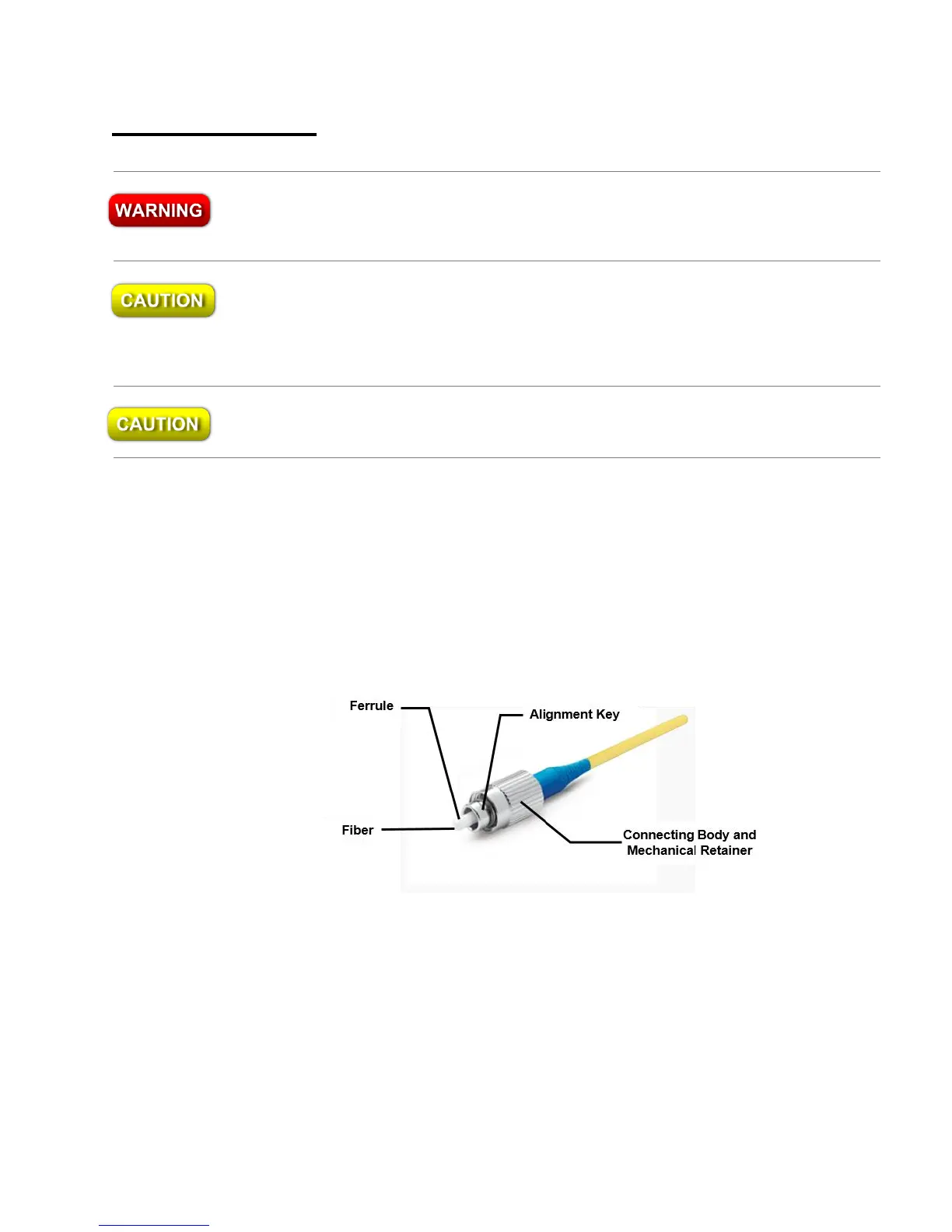
key on the fiber-optic patchcord’s connector (Figure 3.2) is properly seated in the
slot of the input connector.
Figure 3.2: Basic Components of an FC/PC Fiber-Optic Connector
3 Tighten the mechanical retainer with a light to medium finger-tightness.
Exceeding this torque may result in a poor connection or may damage the
connector.