Model 428 User’s Manual APPENDIX D – MONITOR PORT
Bristol Instruments, Inc. 65
APPENDIX D – MONITOR PORT
The Monitor Port on the rear panel of the 428 Multi-Wavelength Meter provides a
combination of analog and digital signals for observing the interference fringe signals and
measurement timing signals using an oscilloscope. The Monitor Port uses a 9-pin,
female, D-sub style connector shown in Figure D-1 and with a pinout described in the
table below.
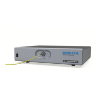
Figure D-1: Monitor Port
Reference laser sinusoidal interference fringe signal.
Input laser sinusoidal interference fringe signal.
Scanning Window Trigger is a digital pulse with a duration that
defines the maximum measurement interval for the
interferometer scan. It goes active (H=active) during the
allowed measurement interval.
Zero Optical Path (ZOP) is a digital signal that indicates the
location (timing) of equal path length in the arms of the
interferometer. For scans of one direction, a positive edge
indicates ZOP. For scans of the other direction, a negative
edge indicates ZOP.
Scanning Window digital output is derived from the amplitude
of the input laser fringe signal. When the p-p amplitude of this
signal exceeds 1 volt, within the Trigger interval and before or
spanning the ZOP transition, the Window is active (H=active).
Depending on the character of the input laser fringes, there
may be several Windows during a Trigger, but the first Window
period to terminate after the ZOP transition is the only “Valid
Window” used for the measurement.