Model 428 User’s Manual INITIAL INSTRUMENT SETUP
Bristol Instruments, Inc. 8
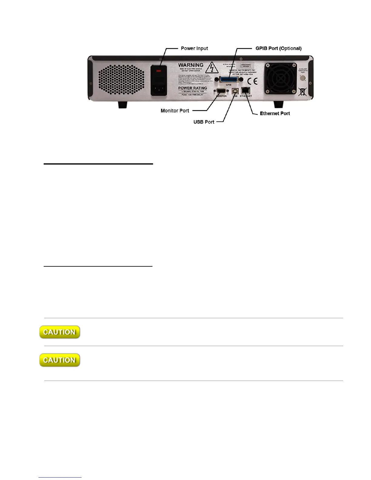
Figure 2.1: Back Panel
Signal Output Connections
The 428 Multi-Wavelength Meter has the following connections for signal output and
communications. These connections are located on the instrument’s back panel
(Figure 2.1).
USB Port – Interface to a PC for instrument control and data reporting.
Ethernet Port – Interface to a PC or network for instrument control and data reporting.
GPIB (Optional) – Interface to a PC for instrument control and data reporting.
DB-9 Monitor Port – Used to monitor the interference fringe pattern and
instrument timing signals with an oscilloscope. A full description is provided in
Appendix D.
Rack Mount Kit Installation
The 428 Multi-Wavelength Meter can be mounted in a standard 19” instrument rack by
attaching the rack mount brackets. These brackets are attached to the front bezel of the
system using the 8-32 x 5/8” flat head socket screws included in the rack mount kit. For
proper fit, the feet under the chassis may be removed.
Do not reinsert the screws once the feet are removed. Damage to the internal
components of the instrument may result.
When the system is mounted in an enclosed instrument rack, be careful not to block the
fan on the back panel. Adequate ventilation must be provided inside the instrument rack
to prevent overheating.