5
2.0 Brivis Touch Controller Installation
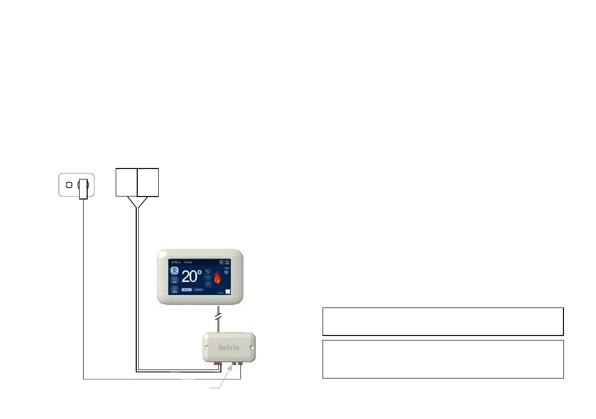
The Brivis Touch Controller is connected to a compatible Brivis
appliance through the Interface Module. A 20m, four core, Power
& Communication Loom (P&C Loom), connects the Brivis
Touch Controller to the Interface Module. The Power
Transformer (12VDC) supplies power to the Interface Module.
Diagram 4: Connection Diagram
To connect the Brivis appliance to the Brivis Touch:
1. Determine location of the Brivis Touch.
2. Determine location of the Interface Module.
3. Install the Brivis Touch.
4. Install Interface Module.
5. Connect Interface Module to Appliance.
2.1 Location of the Brivis Touch
For proper operation the Brivis Touch must accurately monitor the
temperature in the space it controls.
Guidelines:
The Brivis Touch should be mounted:
Approximately 1.5m above floor level (ensure hole into wall
cavity is properly sealed).
Close to the centre of the living space on an internal wall.
On a section of wall that does not contain pipes, electrical wires,
antenna cables or ductwork.
The Brivis Touch should NOT be mounted:
Where it is exposed to direct sunlight or other heat sources
which may cause a false reading.
Near or in the path of supply air outlets or return air grilles.
On outside walls, near windows or doors leading to outside.
In areas with poor air circulation such as recesses or behind
doors.
Do not install the wiring with the power turned on, as the
not be covered under warranty.
When there are multiple Brivis Touch Controllers on a
system, always ensure that the location of each is within 20m
Loom, 20m (supplied)
0.75mm² figure-8 cable
(field supplied)
Appliance
(field supplied)
12VDC 1.5m loom
(supplied)
(supplied)
Module
(supplied)
(field supplied
GPO)