6
2.2 Location of the Interface Module
The Interface Module shall be located within 1.5m of a 10 Amp
240 volt fixed switched socket outlet. The Brivis Touch shall be
within 20m of the Interface Module.
2.3 Install the Brivis Touch
The Brivis Touch Backing Plate must be installed prior to
mounting the Brivis Touch.
To mount the Backing Plate do the following:
1. Remove the Brivis Touch Backing Plate from the packaging.
2. Use Backing Plate as a template and mark the two Mounting
Hole centres and the Loom Access hole centre, refer to
Diagram 5.
3. Install the supplied wall Plug Kit in the Mounting Hole
locations. For drill sizes refer to Diagram 5.
4. Fasten Backing Plate with wall Plug Kit screws.
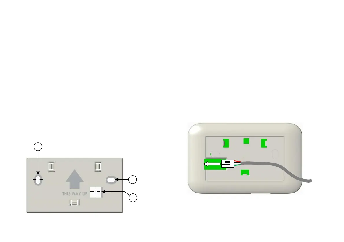
Diagram 5: Brivis Touch “Backing Plate”
To mount the “Brivis Touch”:
1. Run the supplied P&C Loom from the Touch to the
Interface Module.
2. Draw the loom from the wall cavity and feed through the
P&C Loom Access opening on the Touch Backing
Plate.
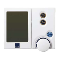
3. Connect the P&C Loom terminal (female) to the Touch
terminal (male) before mounting it on the wall, refer to
Diagram 6.
4. Push excess cable back into the wall cavity and mount
Touch onto the Backing Plate. The three Male Clips on
the Backing Plate will engage and secure the Touch,
refer to Diagram 7.
Diagram 6: Brivis Touch Controller P&C Loom Connection
Drill size ø6.0mm
Access
Drill size ø13