Brivo ACS300 Installation Manual Page 18
© 2017 Brivo Systems LLC. All rights reserved. Rev 1
WARNING: Relay Amp Limit
THERE IS A 6 AMP 28 VOLT DC LIMIT ON THROUGH CURRENT FOR
ALL RELAYS.
5. If used, wire the AUX INPUTS terminal block.
a) The AUX INPUT 1 and AUX INPUT 2 terminals are contact closure type inputs.
b) The terminals can be used for a variety of purposes, and are programmed
through Brivo OnSite.
6. If using Wiegand readers, wire the reader terminals to the DOOR 1 and DOOR 2
terminals on the left side of the ACS300 board.
7. If using OSDP RS-485 readers, wire the reader terminal to the RS-485 terminal on the
upper left side of the ACS300 board.
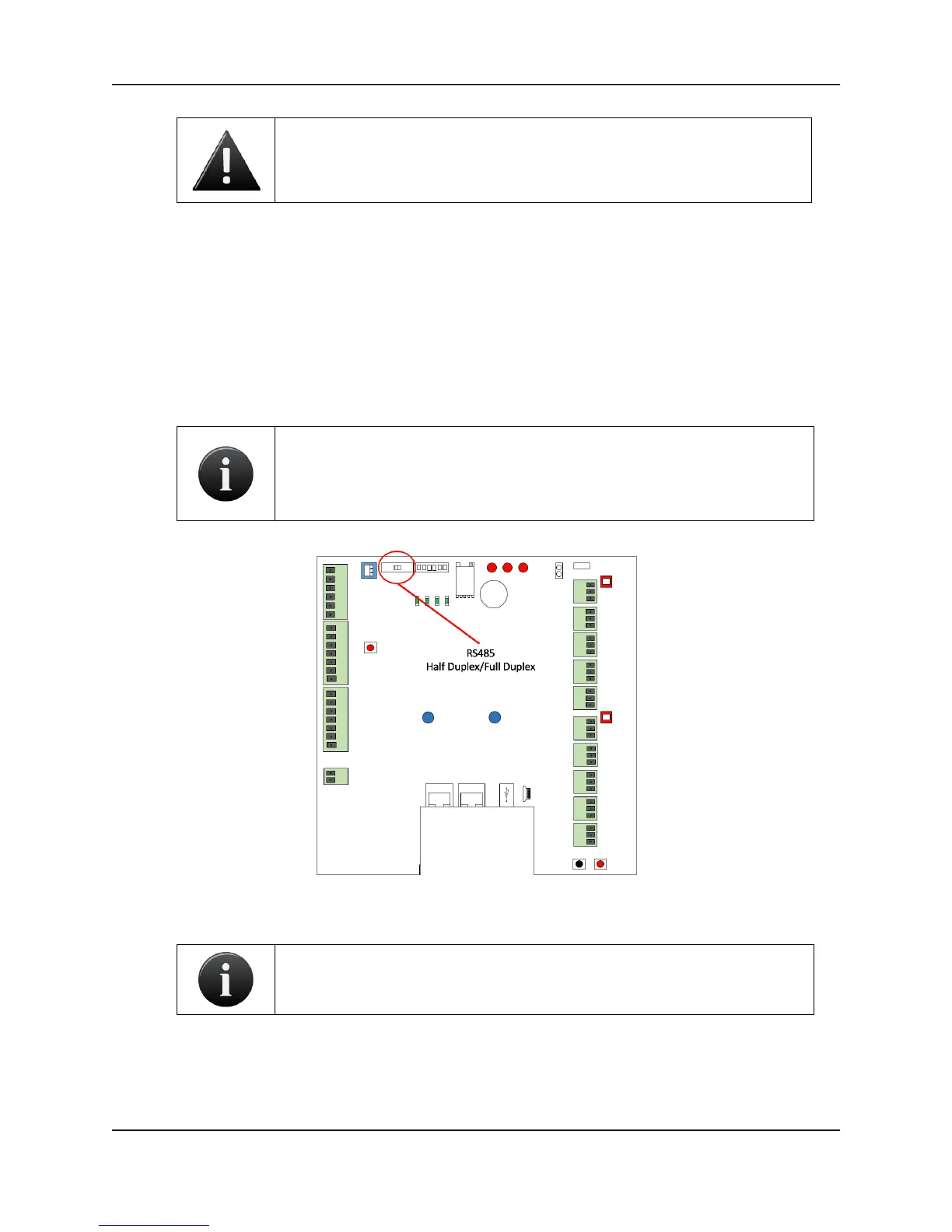
NOTE: The ACS300 board’s factory default setting is Half-Duplex
communication when using RS-485 reader functionality. In order to switch
to Full-Duplex communication, move the HDX/FDX switch to the Full-
Duplex position.
RS-485 Full Duplex/Half Duplex Switch Location
NOTE: RS-485 bus requires termination. The RS-485 termination switch is
located in the upper left hand corner of the ACS300.