53-1004408-11 Installation Guide
Brocade
®
G610 Switch Hardware Installation Guide
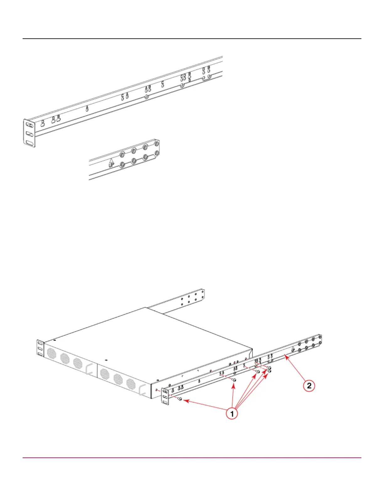
Figure 14: Enlarged View of the Front Right Bracket Showing Labels
1. Position the right front bracket with the flat side against the right side of the device as shown in the following figure. Be
sure that the arrowhead is pointing upward when mounted.
2. Insert two 8-32 x 5/16-in. screws into one of the pairs of vertically aligned holes in the bracket and then into the pair of
holes on the side of the device.
3. Insert each of three additional 8-32 x 5/16-in. screws through the holes in the bracket and into the corresponding holes
in the device as shown in the following figure. Be sure to use holes with the same label. Tighten all 8-32 x 5/16-in.
screws to a torque of 15 in.-lb (17 cm-kg).
4. Repeat step 1 through step 3 to attach the left front bracket to the left side of the device. Again, be sure that the
arrowhead is pointing upward when mounted and that you are using the holes with the same labels as you used on
the right side.
Figure 15: Attaching the Front Bracket
1. Screws, 8-32 x 5/16 in. Panhead Phillips (five per side)
2. Bracket, Front Right
53-1004408-11
35