Brocade FastIron GS and FastIron GS-STK Hardware Installation Guide 25
53-1001783-01
Installing a redundant power supply
2
DRAFT: BROCADE CONFIDENTIAL
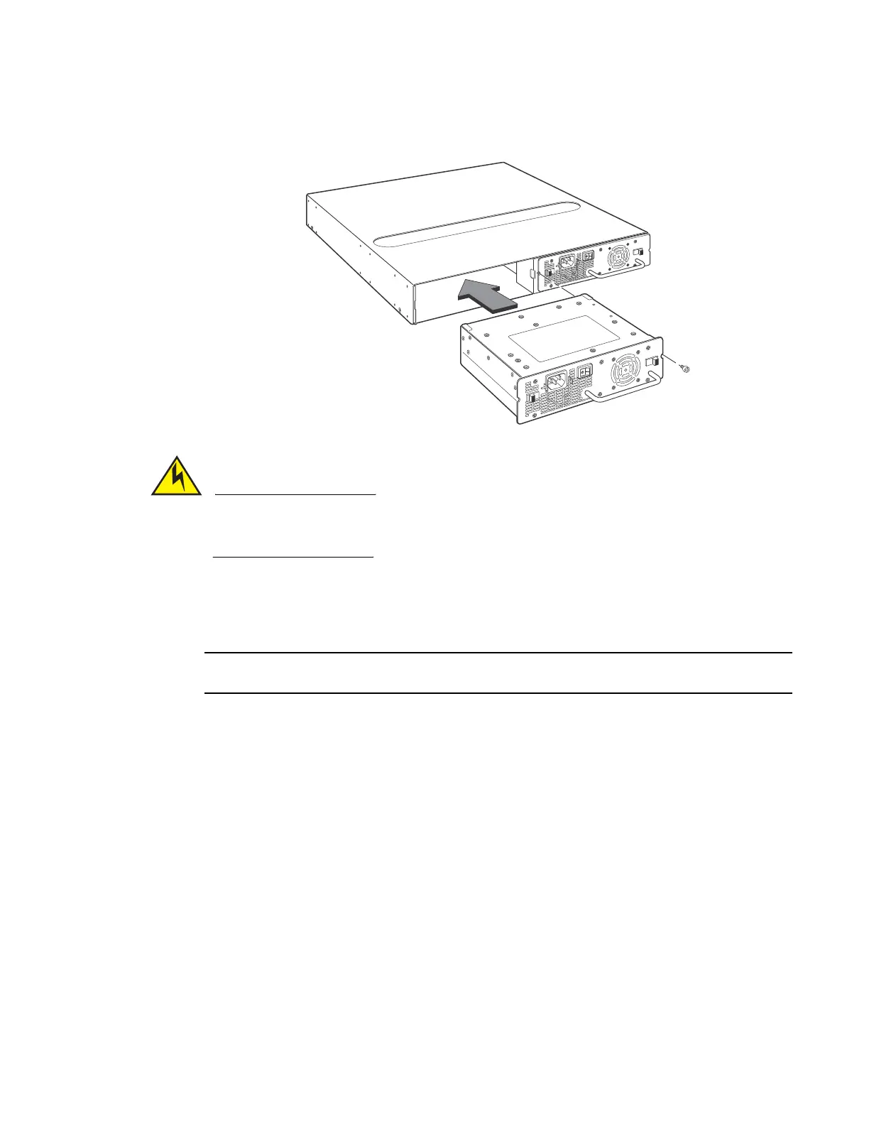
FIGURE 19 Inserting the Power Supply
Make sure you insert the power supply right-side up. It is possible to insert the supply upside
down, although the supply will not engage with the power backplane. The power supply is
right-side up when the power connector is on the left and the fan vent is on the right.
5. Press the two latches near the edges of the supply outward to lock the supply in place.
6. Replace the power supply locking screw.
7. Install the power cord, and secure it wIth the retaining bale, as shown in Figure 20.
The edges of the power supply panels will extend approximately .25 in.beyond the side of the device.
 Loading...