3-18
PRESSURE SETTINGS
The hydraulic system is divided into two pressure circuits, each having its own protective
adjustable relief valve in the inlet sections of the control valve. The functions operated
by the control valve sections require different pressures for different functions. These
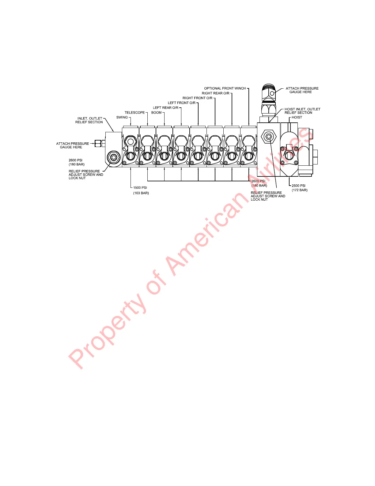
are shown below:
1. Winch Circuit -- 2500 PSI (172 bar) at full flow.
2. Boom and Outrigger Circuit -- 2600 PSI (180 bar) at full flow.
3. Boom swing work ports -- 1500 PSI (103 bar) at full flow.
A good quality pressure gauge with at least a 3000 PSI (207 bar) scale is required to
make adjustments properly. A 3000 PSI (207 bar) working pressure hose with adapters
to fit the 3/8" tube pressure ports is required to install the gauge where it can be read
easily.
The following procedures are suggested when taking pressure readings:
WINCH CIRCUIT:
Remove the 3/8" JIC cap from the fitting on the front of the control valve near the winch
control section and install a 3000 PSI (207 bar) pressure gauge. To obtain full flow
reading, run pump full speed, pull winch control to RAISE position and hold until
maximum reading is made. The anti-two-block override switch must be actuated. If a
pressure of 2500 PSI (172 bar) is not possible, check the following:
1. Broken mechanical connection to the pump shaft.
2. Low oil level in the reservoir.
3. Clogged suction filter or shutoff valve not fully opened.
4. Valve spool linkage not allowing control valve to fully open. Valve spool should
move 3/8" (10mm) each way from neutral position.
5. Anti-two-block system malfunction.
6. Adjust relief valve by loosening nut on top of relief cartridge above winch gauge port
and turning socket-head screw clockwise to increase pressure or counter-clockwise
to lower pressure.
7. Foreign particle in pilot operated relief.
8. Worn or defective hydraulic pump.
Property of American Airlines
 Loading...


