Brookeld Engineering Labs., Inc. Page 2 Manual No. M02-313E1209
TABLE OF CONTENTS
I. INTRODUCTION ..................................................................................................................... 3
I.1 Components ....................................................................................................................................................3
I.2 Utilities ...............................................................................................................................................................4
I.3 Specications ..................................................................................................................................................4
I.4 Dimensional Details ...................................................................................................................................... 6
I.5 Installation ........................................................................................................................................................7
I.6 Safety Symbols and Precautions ..............................................................................................................
8
I.7 Key Functions .................................................................................................................................................. 9
I.8 Viscosity and Temperature Display ..........................................................................................................9
I.9 Cleaning ..........................................................................................................................................................10
II. GETTING STARTED .............................................................................................................. 11
II.1 Power ON ........................................................................................................................................................11
II.2 Cone Spindle Selection and Setting .....................................................................................................12
II.3 Speed Setting ................................................................................................................................................13
II.4 Temperature Control Setting ...................................................................................................................14
II.5 Hold Time Settings ......................................................................................................................................14
II.6 Run Time .........................................................................................................................................................14
II.7 Printing ............................................................................................................................................................15
II.8 Run and Stop Keys .......................................................................................................................................15
II.9 Parameter Display ........................................................................................................................................16
III. OPERATION .......................................................................................................................... 17
III.1 Full Scale Range and Accuracy of Measurement ...............................................................................17
III.2 Accuracy of Viscosity and Temperature ..............................................................................................18
III.3 Calibration Verication ..............................................................................................................................20
III.4 Cone Calibration ..........................................................................................................................................22
III.5 Repeatability .................................................................................................................................................24
III.6 Making Viscosity Measurements ...........................................................................................................25
III.7 Computer Control .......................................................................................................................................26
APPENDIX A - Variables in Viscosity Measurement .....................................................................................28
APPENDIX B - Communications .........................................................................................................................30
APPENDIX C - Warranty Repair and Service ...................................................................................................34
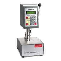
This manual intended for use with CAP 2000+ series viscometers which have serial
numbers beginning with a prex of “CPN”.
CAP1000 and 2000 Viscometers with a serial number prex of “CP” require a dierent
manual. Please contact Brookeld or your authorized dealer/representative to obtain
this manual
.