Brookeld Engineering Labs., Inc. Page 7 Manual No. M02-313E1209
I.5 Installation
DO NOT lift the viscometer by the handle or head! LIFT only by the base console
or column!
1) Set the viscometer on a clean level bench surface.
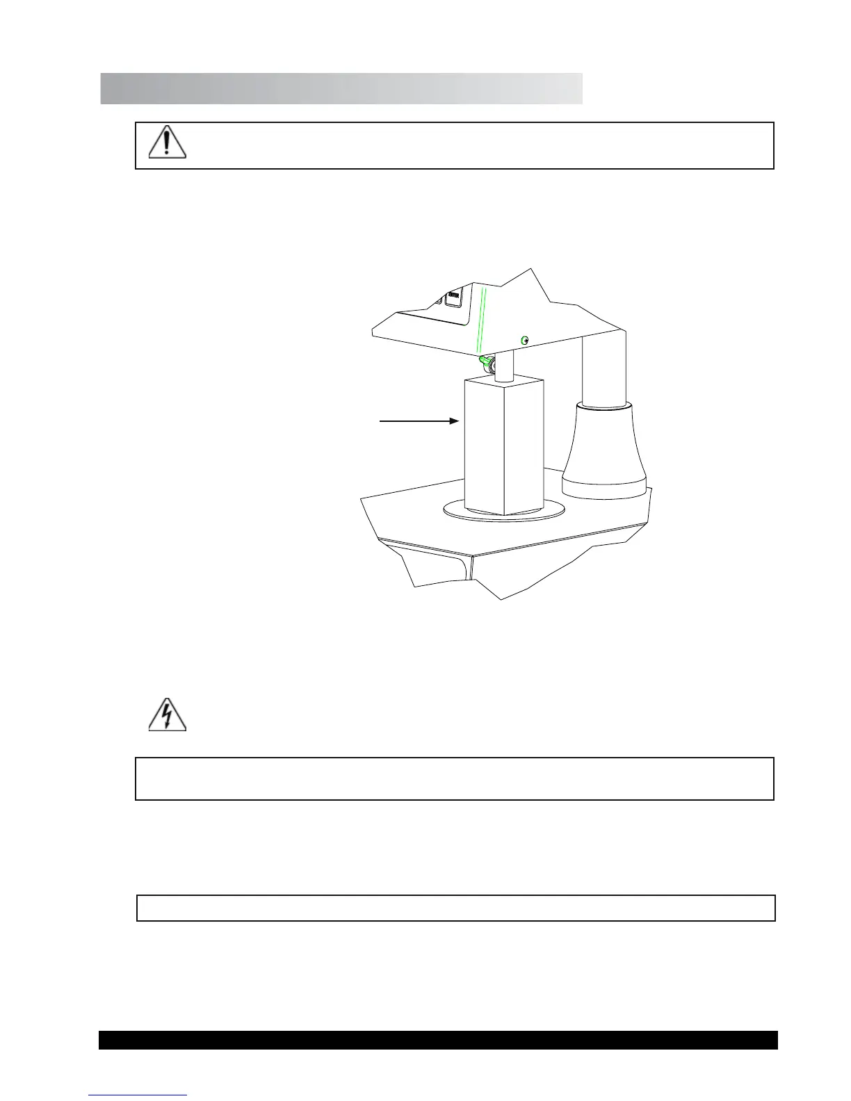
2) Remove shipping foam insert from the plate area on the CAP Viscometer
. Store the
foam insert for future use when shipping or transporting CAP Viscometer.
Foam Insert Used
When Shipping
CAP Viscometer
Figure I-2: Detail of Foam Insert
3) Verify that the viscometer’s power requirements match your power source BEFORE con-
necting it to power.
The AC input voltage and frequency must be within the appropriate range as shown
on the back of the viscometer head .
Note: The CAP Viscometer must be earth grounded. Use the three (3) wire power cord!
Do not alter!
4) Connect the power cord to the viscometer and to the power supply (source).
5) If using a printer, connect the printer cable to the printer port and printer.
Note: Ensure that both the printer and the CAP 2000+ are off when connecting cables.