LK3-B430E Mark II
7
3. MECHANICAL DESCRIPTIONS
!4
u
!1
i
r
e
w
q
y
!0
o
t
!3
!2
!5
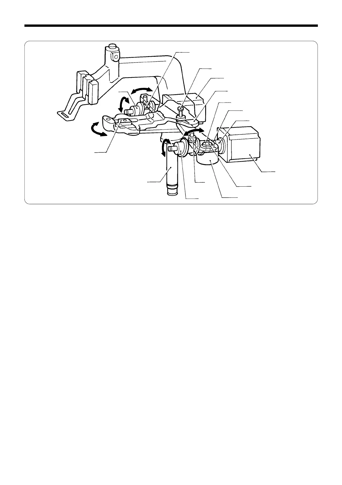
3-4. Feed mechanism
(Y direction)
1. When the Y-pulse motor q operates, coupling hub 6.35 w, the coupling spacer e, and coupling hub 8 r
transmit the motion to feed cam Y t.
2. Feed cam Y t is connected to the Y-feed lever !0 pivoting on the tack width lever shaft y, which is
connected to the feed bracket i with the tack width lever u, via the feed cam roller o.
3. The motion of the Y feed lever !0 is transmitted to the feed bracket i via the tack width lever shaft y.
(X direction)
1. The motion of the X-pulse motor !1 is transmitted to feed cam X !2 with the same couplings as for Y
direction.
2. One end of the X feed lever !3 is positioned on feed cam X !2 along with the feed cam roller !4, and the
other is attached to the feed bracket i along with the slide block !5. When feed cam X !2 moves, the feed
bracket i oscillates, pivoting on the tack width lever shaft u.
Sewing patterns are created through combinations of X and Y movements shown above.
 Loading...