3-70
Confidential
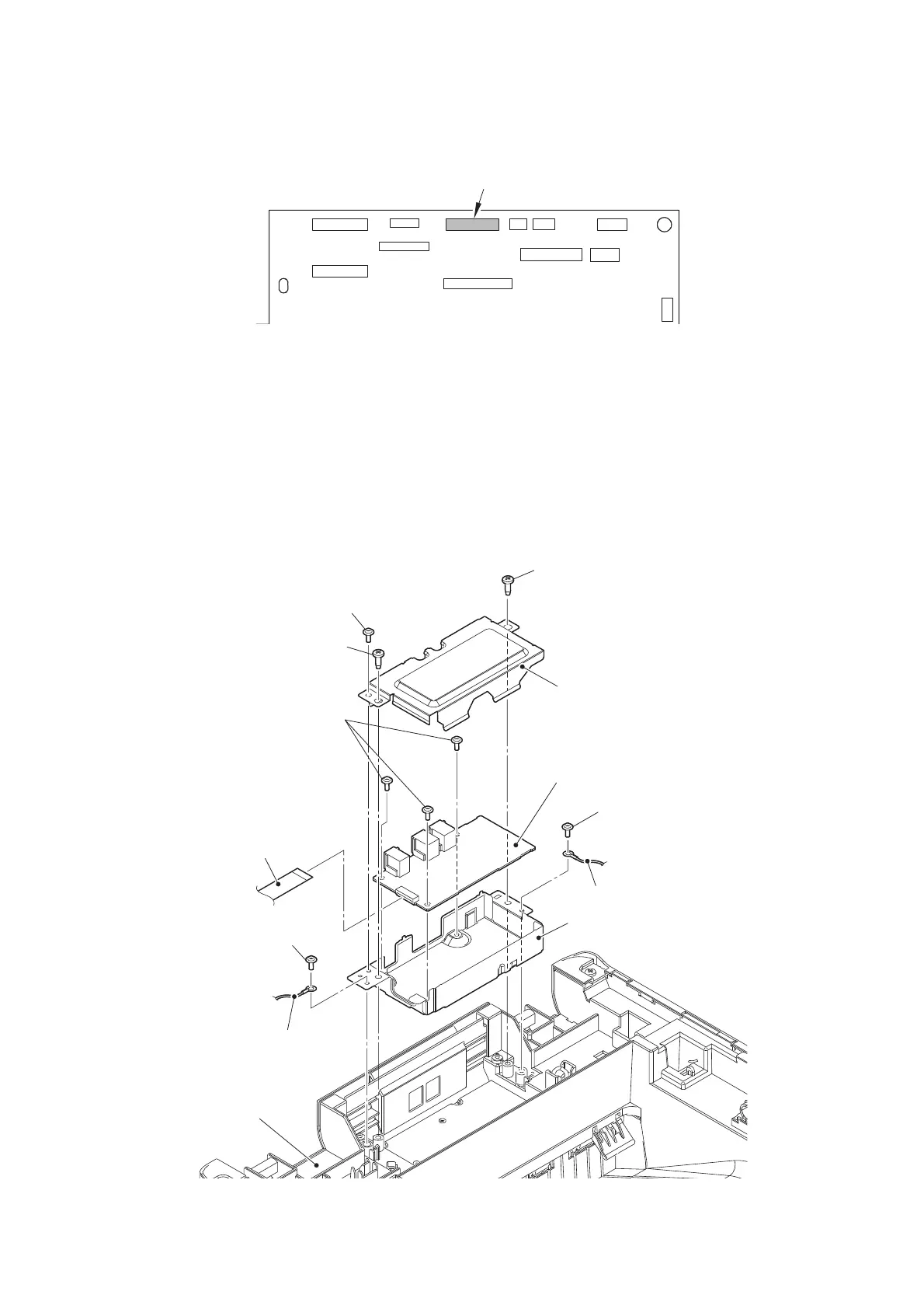
9.15 Modem flat cable / Modem PCB
(1)
Disconnect the Modem flat cable from the Main PCB, and release it from the securing fixtures.
Fig. 3-52
Harness routing: Refer to “2. Top side of the machine (ADF unit, Document scanner unit,
Modem unit), 8. Left side of the machine (Modem unit)”.
(2) Remove the two Screw cup M3x8 (black) screws to remove the Modem ground wire L/R
from the Modem plate.
(3) Remove the two Taptite bind B M4x12 screws to remove the Modem plate from the Joint
cover ASSY. Disconnect the Modem flat cable from the Modem PCB.
(4)
Remove the Screw cup M3x8 (black) screw to remove the Modem shield cover from the Modem plate.
(5)
Remove the three Screw cup M3x8 (black) screws to remove the Modem PCB from the
Modem plate.
Fig. 3-53
Taptite bind B M4x12
Joint cover ASSY
Taptite bind B M4x12
Screw cup M3x8 (black)
Modem PCB
Modem plate
Screw cup M3x8 (black)
Modem ground wire L
Modem ground wire R
Modem flat cable
Screw cup M3x8 (black)
Screw cup M3x8 (black)
Modem shield cover