3.1
3.2
3.3
3.4
3.5
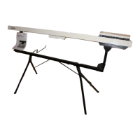
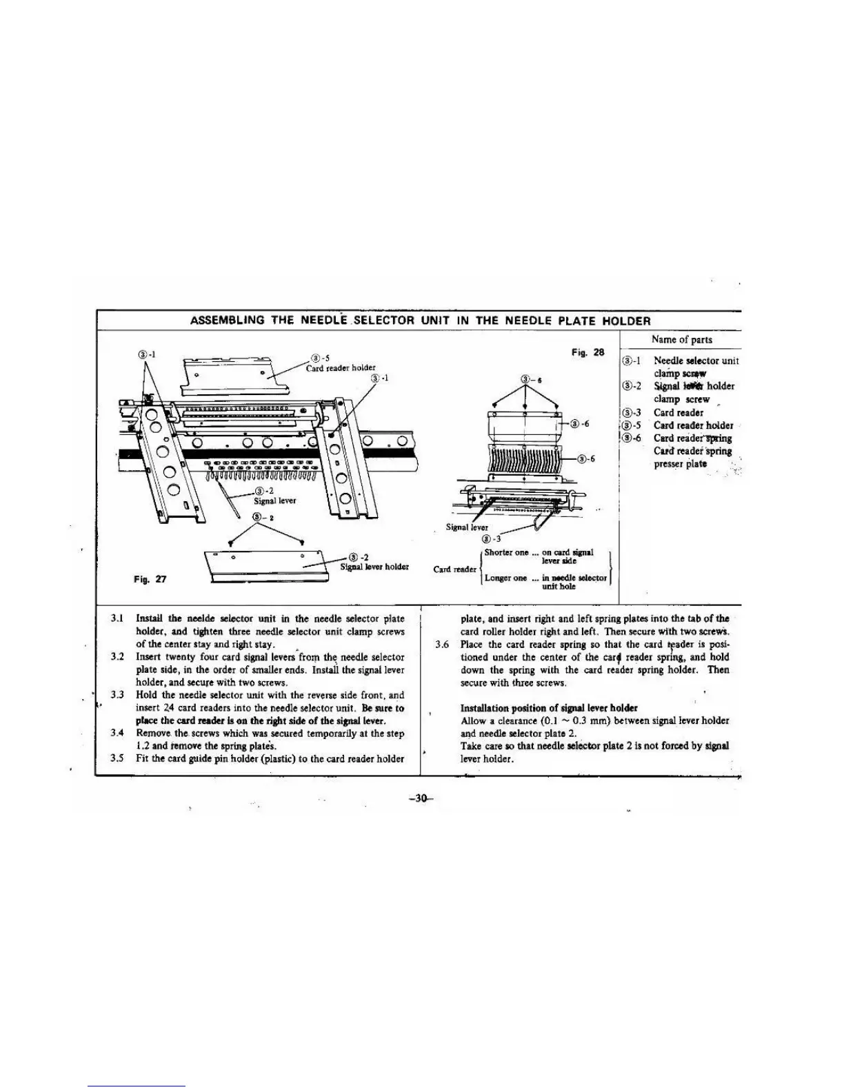
ASSEMBLING THE NEEDLE .SELECTOR
UNIT
IN THE NEEOLE PLATE HOLDER
®·I
Fig.
28
(~
- I
®-2
®·3
;@·S
!®
-6
I
Name
of
parts
Needle
sel~tor
unit
clainp~
S.lgnal
- holder
clamp screw •
Card reader
Card
reader holder •
Card
reidei'lprin,
Card reader lprina
pres1er plate
\
..
0
·~®-2
\:::::::===~:::=~
SJa!W
lover
holder
i,
-
Carel
TOader
\
Shorter one ... on can!
"'"a!
I
lever side
Fig.
'D
Install
the
neelde aelector unit
in
the needle selector plate
holder, and tighten three needle selector unit clamp screws
of
the center stay and right stay. •
Insert twenty four card
sil!llal
Ieven from
th~
needle selector
plate side, in the order
of
smaller ends. Install the signal lever
holder, and secure with two screws.
Hold the needle selector wtit with the reverse side front, and
insert
2.4
card readers into the needle
sel
ector unit.
Be
sure
to
place
the
card reader
II
011 the right side
of
the rianaJ lever.
Remove. the. screws which war secured temporarily
at
the step
1.2 and temo•e the spring plates.
Fir the card guide
pin
holder (plastic)
to
the card reader holder
3.6
-30-
Lonpr
one
•••
in
needJe
.
~'
uDlt
hole
plate, and insert right and left spring plate$ into the tab
of
the
card roller holder ri
gh
t and left. Then secure wfth two
sae\VS.
Place
the card reader spring
so
that
the card *fader is
posl·
tioned under the center
of
th
e
carf
reader spring, and hold
down the spring with the card reader spring
ho
lder. Then
secure with lhree screws.
Installation position
of
sipallever
holder
Allow
a clearance (0.1 - 0.3
mm)
between signal. lever holder
aJ!d
needle selector plate 2.
Take care so
that
needle
ae
lO!:
tor
plate 2
Is
not
forced
by
slplal
lever holder.
 Loading...