PG.
INSPECTION
After the boards are assembled and soldered, each board is inspected to check all operating parameters and
all technical specifications.
INSTALLATION
The user must be extremely careful when installing the controller.
The procedure is described step by step:
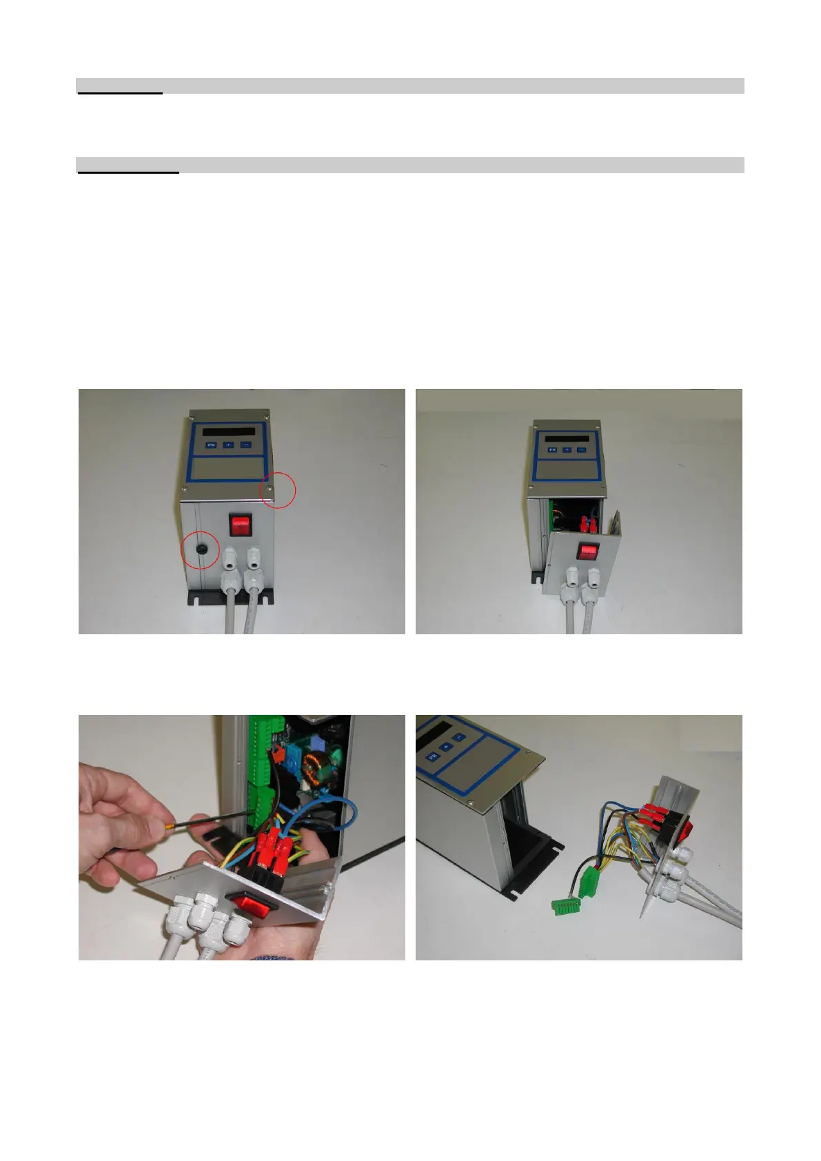
1) If necessary, attach the device to a support bracket as shown in Fig. 01. and Table 03.
2) Open the controller by unscrewing the two screws marked with a circle as shown in Fig. 03.
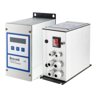
3) Pull the lower panel of the controller outward as shown in Fig. 04.
4) Remove the terminal board with a screwdriver so that the wires can be connected easily. See Fig. 5 and
6.
5) Connection of the power supply and peripheral devices differs according to the type of controller used.
The CFF and CFV controllers use the same terminal board for connection; the DCFF uses a different
terminal board. For connection of the power supply and peripherals (such as Sensors or Probe), see Fig.
07 for CFF and CFV, Fig. 08 for DCFF and Fig. 09 for CFF15A.