11
BOAT RIGGING
INFORMATION DISPLAY SYSTEMS
1
INFORMATION DISPLAY
SYSTEMS
Engine Monitor System
All remote controlled outboards must be equipped
with an engine monitoring syste m to warn the
operator of conditions that could damage the out-
board.
The eng ine monitor system includes sensors on
the outboard and oil tank, a warning horn, a dash-
mounted display, and related wiring.
The outb oard’s EMM sen ds information about
monitored functions to:
• SystemCheck gauges, or
• An I-Command or ICON display.
IMPORTANT: Operating the outboa rd without
an engine monito r will void the warranty for fail-
ures related to monitored functions.
SystemCheck Gauges
SystemCheck g auges a re u sed with mechanical
remote control systems only.
SystemCheck gauges receive monitored informa-
tion fro m the outboard throu gh a Modular Wiring
System (MWS) harness.
Refer to SystemCheck (MWS) Harness Con-
nections on p. 12.
I-Command Displays
I-Command dig ital displays are designed spe cifi-
cally fo r NMEA 2000 cer tified Evinrude E-TEC
outboards. Th ese displays provide enh anced
engine and bo at p erformance information . Multi-
ple f unctions a re integra ted into th e e asy-to-use
displays. Additional displays and accessories can
be added with the plug and play design.
I-Command information displays can be used with
either a mechanical remote control system or with
an Evinrude ICON system. For complete installa-
tion instructions, refer to I-Command Installation
Guide.
When inst alling an I-Command ne twork, remem-
ber:
• A termina tor must b e in stalled at each end of
the network
• There should be no ope n o r unu sed network
device connectors
• The network sho uld b e grou nded a t a single
location only
• A maximum of 50 devices ca n be att ached to
the network *
• The distance betwee n any two po ints on the
network must not exceed 100 meters (328 ft.).
* The EMM on Evinrude E-TEC outboards has a
load equivalency number of 1. Less than 50 mA of
the network’s power is used by the EMM.
If a mechanical con trol is u sed, the I-Command
network re ceives mo nitored in formation through
an I-Command network harness con nected
directly to the outboard’s EMM. An I-Command
Ignition and Trim harness is required to carry start,
stop, and trim signals to the outboard.
Refer to I-Command Harness Connections
With Mechanical Remote Control on p. 13.
If a n ICON control is use d, the I-Command ne t-
work receives monito red infor mation throug h the
ICON control network gateway.
Refer to Evinrude ICON / I-Command Harness
Connections on p. 14.
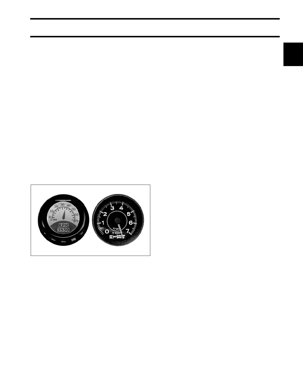
Typical I-Command and SystemCheck gauges 007988