44
OUTBOARD INSTALLATION
LIFTING THE OUTBOARD
LIFTING THE
OUTBOARD
Lifting Fixtures
Remove shipping carton.
Use correct Lifting Fixture to lift outboard:
90° V6 MODELS
Position lifting tool on flywheel and seat the three
screws completely.
Fasten appropriate chain hoo k to eye of too l.
Carefully hoist outboard with chain and unbolt out-
board mounting brackets from frame.
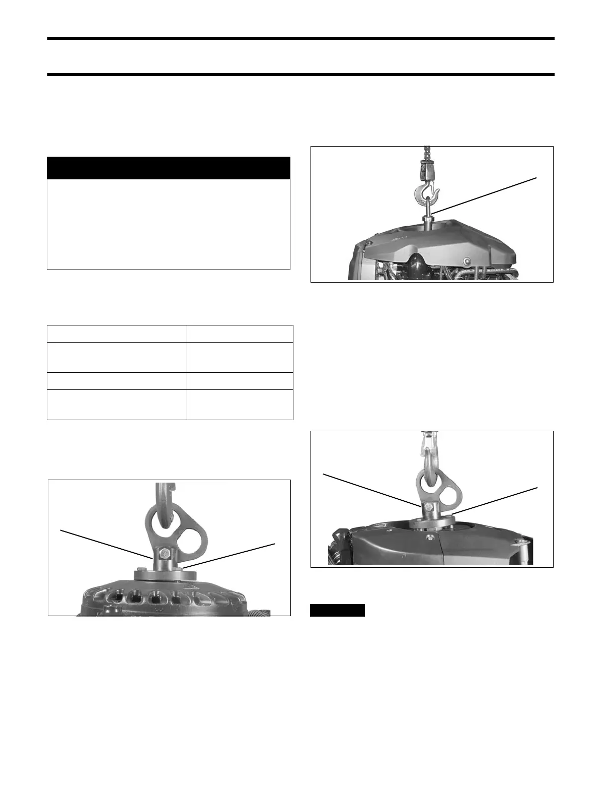
60° V4 AND V6 MODELS
Position lif ting to ol o n cra nkshaft and tig hten th e
center ret aining screw securely using a 1/4 in.
Allen wrench.
Fasten a ppropriate chain hook to eye of tool.
Carefully hoist outboard with chain and unbolt out-
board mounting brackets from frame.
40–90 HP MODELS
With re coil st arter re moved, place lifting too l on
flywheel and sea t the three screws completely.
Refer to RECOIL STARTER REMOVAL in the
correct Service Manual.
Use only the 1 1/8 in. (short)
screws, P/N 398067, included with the tool to
avoid damage to electronic components under
the flywheel.
Fasten a ppropriate chain hook to eye of tool.
Carefully hoist outboard with chain and unbolt out-
board mounting brackets from frame.
A WARNING
To avoid personal injury, make sure the lift-
ing capacity of the hoist is at least twice
the weight of the outboard.
DO NOT allow the lift hook or chain from
the hoist to come in contact with any part
of the engine during lifting.
Model Lifting Fixture
90° V6 P/N 396748 with
1 3/4 in. screws
60° V4–V6 P/N 342672
40–90 HP P/N 396748 with
1 1/8 in. screws
1. Lifting fixture
2. 1 3/4 in. screws
002419
1. Center retaining screw 004945
1. Lifting fixture
2. 1 1/8 in. screws
002098