61
OUTBOARD RIGGING
EVINRUDE E-TEC 60° V MODELS 115–200 HP
3
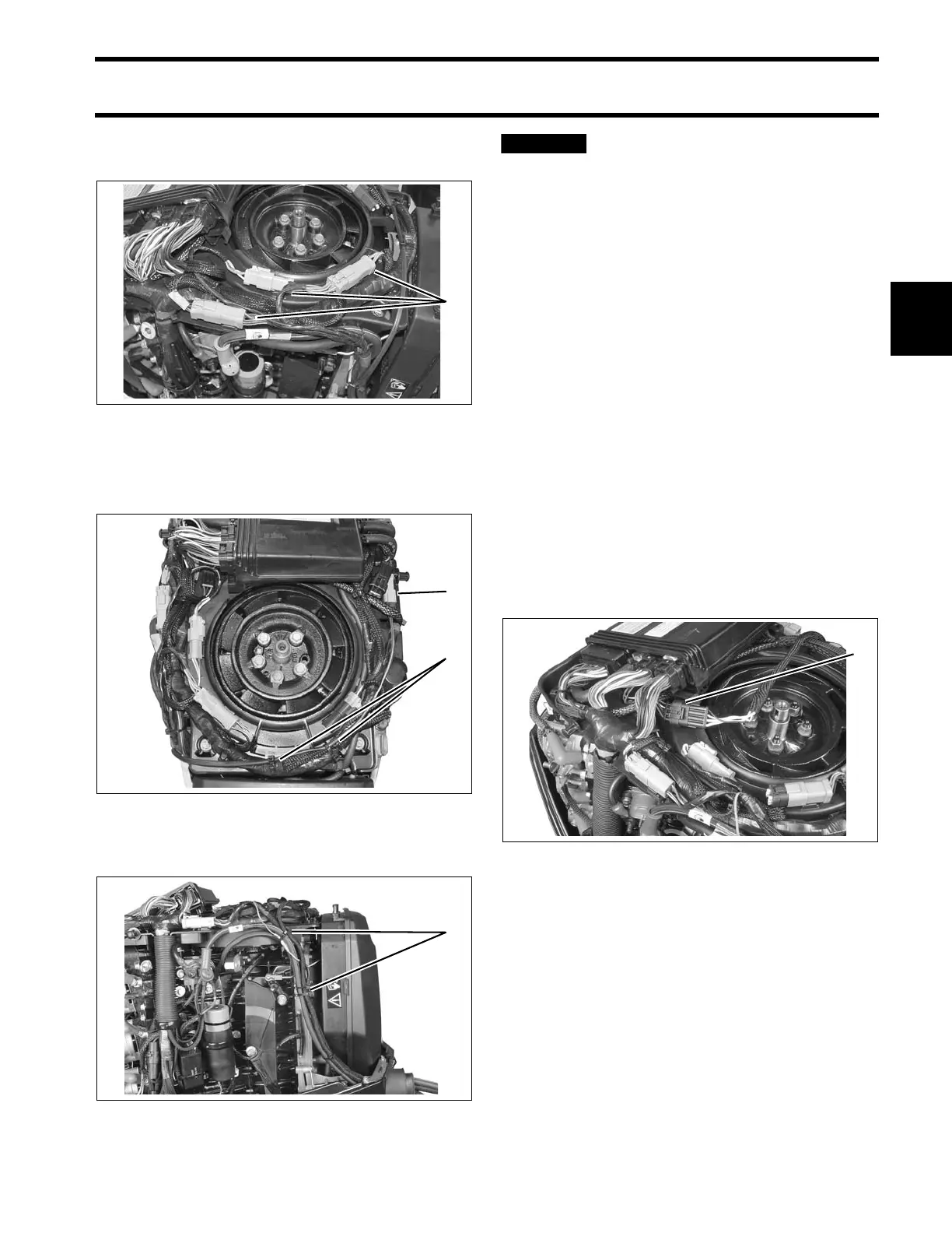
Connect outboard main wire harness to boat wire
harness. Secure connectors in brackets.
Route oil t ank sending unit harne ss around the
front to the po rt side. Se cure all cables with t ie
straps.
Secure all cables with tie-straps.
BE SURE all harnesses and wires
are not pinched, cannot contact flywheel, and
do not interfere with moving throttle or shift
linkages.
Replace flywheel/harness connector cover.
I-Command Network Connections
If the outboard will b e used with I-Command, or
other NMEA 2000 compliant CANbus instruments,
use the following connecti ons to sup ply informa-
tion to the network:
If using an Evinrude ICON control syst em, the I-
Command Engine Interface Cable, Power Supply
Kit, and Ig nition and Trim Harn ess a re n ot
required. Conne ct the I-Command network
directly to the ICON g ateway modu le. Refer to
Evinrude ICON / I-Command Harness Connec-
tions on p. 14.
If using a mechanical control system, connect the
I-Command En gine Interface Cable to the EMM
CANbus connector.
1. Harness connections 004951
1. Low oil sender connection
2. Tie straps
004952
1. Anchor points 005270
1. EMM CANbus connector 005267