63
OUTBOARD RIGGING
EVINRUDE E-TEC 60° V MODELS 115–200 HP
3
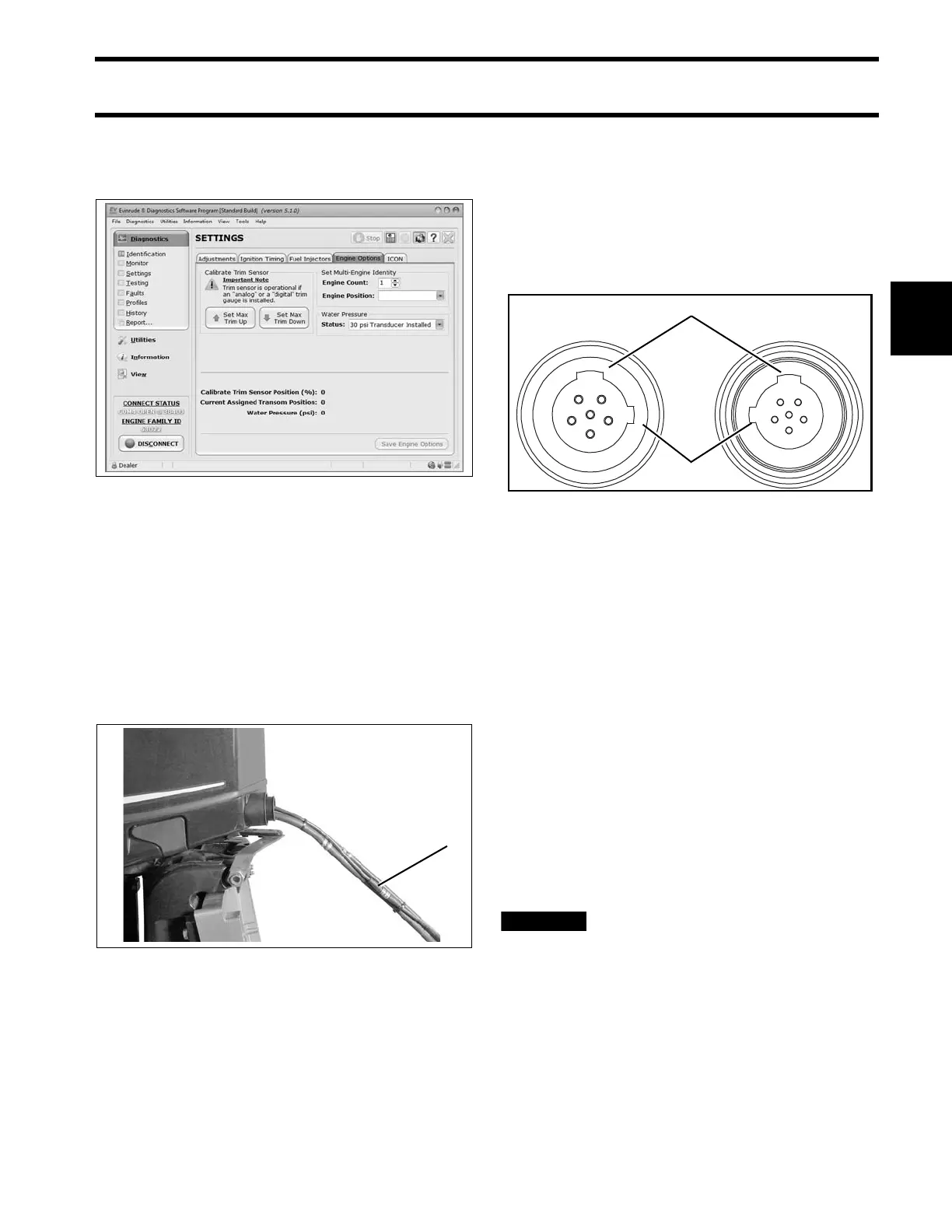
Use Evinrude Diagnostics software to adjust net-
work settings in th e EMM. From the Settings
screen, select Engine Options.
ICON Network Connections
If the outboard is equipped for an Evinrude ICON
control system, con nect the outboard to the net-
work as follows.
Refer to Evinrude ICON / I-Command Harness
Connections on p. 14.
Connect the buss cable from the rear network hub
to the outboard’s network harness.
IMPORTANT: Do not force con nectors or lock-
ing rings. Properly aligned connectors should
assemble easily.
Do not use Electrical Grease on ICON buss cable
connectors.
To assemble the connectors:
• Use the large t abs and small t abs to carefully
align buss cable connectors.
• Carefully align pins and socket s of conne ctors.
Do NOT force connectors together.
• Tighten locking rings of buss connectors fing er
tight. Do NOT use locking rings to force connec-
tors together.
Do not rot ate co nnectors un til t hey a lign. This
could result in a mismatched connection. It is pos-
sible for each pin to enter a socket even if the tabs
are misaligned. Look at the t abs to en sure con-
nector alignment prior to making the connection.
Engine Mo nitor information is distributed to an
ICON or I-Command network through th e ICON
gateway module. Refer to the I-Command Digital
Network Guide, P/N 355008.
The ICON Harne ss an d Relay Kit, P/N 76529 6,
must be used to pro vide power to boat accesso-
ries that requ ire switched B+. This kit is used in
place of connecting accessories to the “A” termi-
nal o f th e key switch. Accessories connected to
the accessory power rela y sho uld not exceed 7
amps.
Do not connect boat accessories to
the key switch of an ICON system. Connecting
accessories to the key switch can cause low
current, resulting in erratic operation of the
remote control system.
For more information, refer to the Evinrude ICON
Remote Control System Installation Guide,
P/N 764952.
Engine Options Screen 008563
1. ICON network connector 008157
1. Large tabs
2. Small tabs
007883