Bruker Daltonik GmbH Instrument Layout
3.1.4 Scout MTP Ion Source
P2
Electrode
Lens
arrangement
CID cell
Laser beam
Lighting &
camera
Ion flight
Ground
potential
P1
Target
plate
x-y-
stage
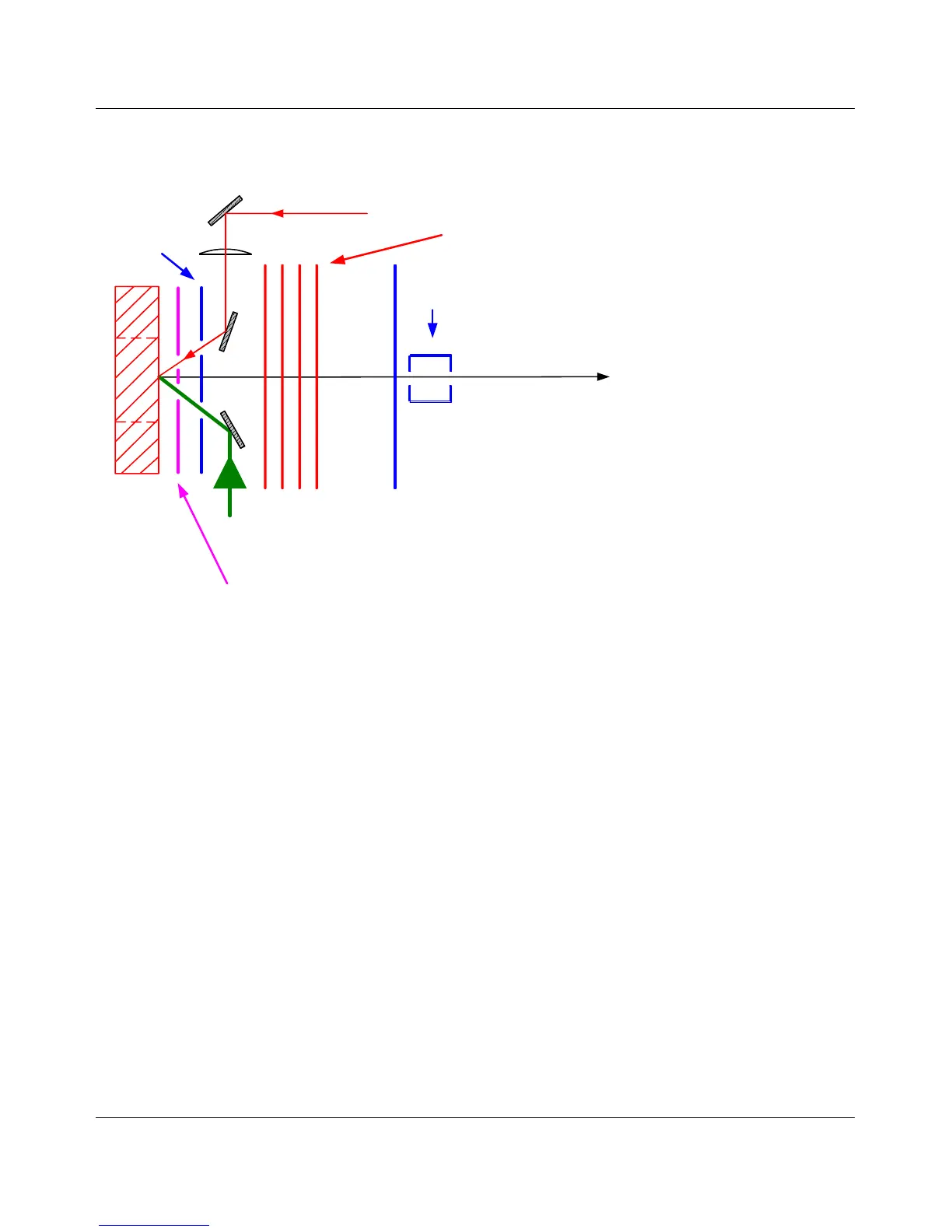
Figure 3-4 Scheme of the time-lag focusing ion source of the “flex”-series
The ion source (Figure 3-4) is the part of the mass spectrometer where ions are formed
using the MALDI technique. The source consists of three main components.
1. The x-y-table accommodates the target plate, transports it into the ion source,
and moves the target inside on x-y-coordinates, according to the selected shot
position.
2. The vacuum lock inserts the target from atmosphere to the high vacuum.
3. The ion optics consists of the positively or negatively charged MTP target plate
(P1), a second voltage plate (P2) for time lag focusing and a grounded
acceleration electrode. When the laser hits the analyte/matrix mixture the
formed ions are accelerated by the delayed applied electrical field and focused
by a lens system before they leave the source.
CID is an acronym for Collision Induced Dissociation. This term stands for the
procedure when molecules decay by collisions during a passage through a particular
cell that is filled with gas, e.g., Ar. CID has proved to be useful to enhance intensities
of fragments in the low fragment mass range.
ultraflex III User Manual, Version 1.0 25
 Loading...