Bruker Daltonik GmbH Instrument Layout
3.1.5.4 Reflector
The main task of a reflector is to compensate flight times of ions with different energies.
The metastable decay of ions is caused by an energy excess occurring during the
complex MALDI process. Because parents and fragments continue traveling with the
same velocity they hit the linear detector simultaneously thus delivering no fragment
spectrum but a single peak. For fragment mass separation a reflector can be
incorporated into the mass spectrometer to separate metastable ions. Ions of different
masses have different kinetic energies and penetrate to different locations into the
electrical field before they are reflected to strike the reflector detector at different times.
To obtain good mass spectra with a reasonable signal-to-noise ratio the geometry of a
reflector has to fulfill specific electrical and size requirements, mainly with respect to
the dimensions of the flight tube, and type and size of the used reflector detector.
The ultraflex III and other TOF mass spectrometers from the “flex”-series use a
gridless reflector with ion lenses (Figure 3-10). Fragments that would arise inside the
reflector instead of during their flight in the drift region form an undesired high chemical
background.
To minimize residence times of ions inside the reflector, a double stage design is
employed where the first stage is that one with the stronger field strength. As a result
the reflector is shorter and the field free drift length is longer, compared to single stage
TOF reflectors. Also this construction deflects all the smaller fragment ions, which
would otherwise contribute to the background noise. In addition the gridless entrance
lens of the reflector creates a space focusing effect, which increases the sensitivity.
The reflector operates at a potential that exceeds the acceleration voltage of the ion
source by about two kV.
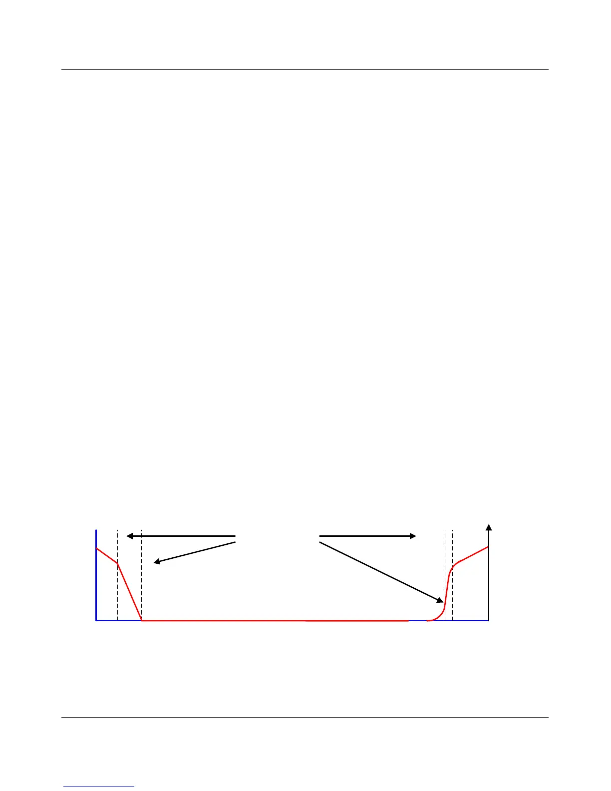
Two stage gridless
reflector
Ion lenses
Ion source
Ground
potential
Acceleration
potentials
Acceleration
potentials
Figure 3-10 Potential distribution in a two stage griddles reflector
ultraflex III User Manual, Version 1.0 35
 Loading...