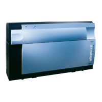
Bruker Daltonik GmbH Operation
At the rear of the instrument are the following connections (Figure 4-1):
CID:
• Collision gas inlet for argon or helium (6 bar maximum) for optional Collision
Induced Dissociation and flushing the collision cell.
• Switch to flush the CID-cell (after changing the collision gas).
• Flushing gas outlet.
Gas supply:
• Compressed air connection to operate the slide valve. Alternatively this port
might be externally connected with the nitrogen inlet for the laser to a common
N2 supply.
• Nitrogen inlet to operate a N
2
-laser (Class IV Laser Product).
• Gas inlet to vent the instrument.
Acquisition:
• Three BNC signal connectors (trigger, detector #1 and #2) for the digitizer
mounted on the PC.
Control:
• BNC connector to provide the video signal of the sample spot to a video capture
card mounted on the PC.
• Serial port to connect the (optional) Twister.
• Serial port to connect the PC (HOST).
Pump:
• Vacuum system exhaust 13 mm (1/2”) ∅ plastic tubing (Tygon), filter mounted
inside. Individual facilities may have safety guidelines, which require ventilation.
It is the responsibility of the user to adhere to the requirements of their
respective facility.
Service Only:
• Key field for the service to lift the cover.
Mains:
•
•
•
The instrument is fitted with an IEC320-C14 mains inlet. Instrument power is
controlled with the mains switch, where:
0 = OFF (vents the instrument)
I = ON
ultraflex III User Manual, Version 1.0 44

 Loading...