Page 50
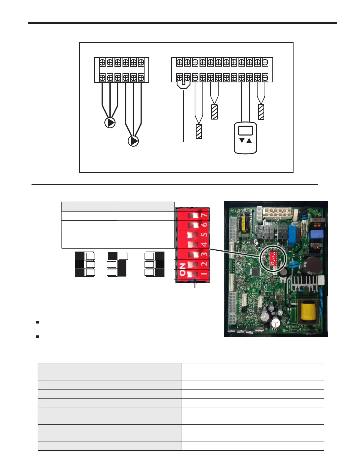
4.18 DIP Switches
System Control Setting
DIP switches 6 and 7 have to be set in the OFF position when the
boiler is running normally.
DIP switches 1, 2, and 3 are system switches and are factory set
to the boiler model and size and should not be touched.
Maximum ame detecting voltage 2.4V
Pre-purge time Tp Maximum 10s, minimum 1s
Safety Time (igniting time) Ts 1.5s
Igniting interval time 10s
Post-purge time Tip 120S (1st : 60s + 2nd 60s)
Over-heating 1,2,3 protection detection time <2s
High & Low Water Level detection time <5s
High & Low Water Level Recover time <5s
Temperature sensor anomaly detection time <3s
APS sensor detection time <3s
800.900.9276 • Fax 800.559.1583 (Customer Service, Service Advisors)
20 Industrial Way, Rochester, NH 03867 • 603.335.6300 • Fax 603.335.3355 (Applications Engineering)
1869 Sismet Road, Mississauga, Ontario, Canada L4W 1W8 • 905.238.0100 • Fax 905.366.0130
www.Laars.com
Document 4387
The FT Series, Heating Only, Gas Conversion Kit
pg 3 of 4
Table B DIP Switch Settings
MBH 100 140 199
These 3 bottom switches must be set per unit SIZE.
9.
Per Table B, set DIP Switch
5 to OFF
for LP Propane.
10.
Turn ON the GAS and WATER supply to the FT.
11.
Turn ON the FT.
12.
Connect a manometer to the manifold pressure port. For dual port manometers, use the positive pressure
side. Check for proper manifold gas pressure. Refer to Table C.
ON OFF
MIN Fire Normal Operation
MAX Fire Normal Operation
NG Natural LP Propane
3” Vent Size
2” Vent Size
Figure D
Gas Valve for 100 & 140 MBH
Gas Valve for
199 MBH
The gas valve on
the smaller models is
mounted vertically.
Manifold Pressure Port
Manifold Pressure Port
Table C
Manifold pressure Propane Gas (LP) Natural Gas (NG)
MFTHW 100
-0.075
˝
WC -0.070
˝
WC
-0.003
˝
WC -0.000
˝
WC
MFTHW 140
-0.130
˝
WC -0.100
˝
WC
-0.004
˝
WC -0.002
˝
WC
MFTHW 175
-0.169
˝
WC -0.129
˝
WC
-0.015
˝
WC -0.015
˝
WC
MFTHW 199
-0.169
˝
WC -0.129
˝
WC
-0.015
˝
WC -0.015
˝
WC
CO
2
value
Propane Gas (LP) Natural Gas (NG)
2˝ VENT 3˝ VENT 2˝ VENT 3˝ VENT
MFTHW 80/100
120/140/175/199
9.5~11% 8.5~10.5%
9~10.5 % 8~10%
Refer to the below table.
13.
Establish a call for heat. You may need to disconnect the outdoor reset if you are making this gas
conversion during warm weather.
Shown is a
Model 140
with 3"
Venting and using
Natural Gas
NOTE: Values are in the range of -.001 to -.35 Inches WC are indicative
of proper set-up. If your readings are outside this range, please call
technical support.
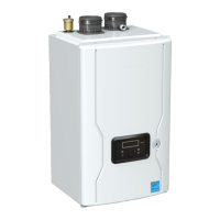
DHW
Circulator
Pump
(14 Gauge Wire)
DHW PUMP
L N GL N G
L W C O
Thermostat or
Endswitch
Outdoor
Sensor
(18 Gauge Wire)
Line Voltage Terminals
Low Voltage Terminals
(18 Gauge Wire)
CH PUMP
T T
O / S
CASCADE
SYSTEM
SENSOR
DHW TEMP
SENSOR
R 0-10V W
(+) INPUT (-)
Low Water
Cutoff
(Factory Jumper Installed)
CH
Circulator
Pump
(14 Gauge Wire)
DHW Temp.
Sensor
(18 Gauge Wire)
Cascade
System
Sensor
(18 Gauge Wire)
4.17 Electrical Wiring Connections (continued)