1. Attach combustion-air pipe to furnace as follows:
a. Determine location of combustion-air intake pipe con-
nection to combustion-air intake housing as shown in
Fig. 34 for application.
b. Reposition combustion-air intake housing plug fitting in
appropriate unused intake housing connection.
c. If required per Table 7, insert perforated disk assembly
(factory-supplied in loose parts bag) in intake housing
where combustion-air intake pipe will be connected. If
half disk set is required, install with shoulder of disk
against stop in combustion-air inlet.
d. Install pipe support (factory-supplied in loose parts bag)
into selected furnace casing combustion-air pipe hole.
Pipe support should be positioned at bottom of casing
hole.
e. Insert 2-in. diameter pipe into intake housing.
NOTE: A 2-in. diameter pipe must be used within the furnace
casing. Make all pipe diameter transitions outside furnace casing.
f. Install casing hole filler plug (factory-supplied in loose
parts bag) in unused combustion-air pipe casing hole.
g. Drill a 1/8-in. hole in 2-in. combustion-air pipe using
hole in intake housing as a guide.
h. Install a field-supplied No. 6 or No. 8 sheet metal screw
into combustion-air pipe.
NOTE: DO NOT OVERTIGHTEN SCREW. Breakage of intake
housing or fitting may cause air leakage to occur.
NOTE: Do not attach combustion-air intake pipe permanently to
combustion-air intake housing since it may be necessary to remove
pipe for service of igniter or flame sensor.
COMBUSTION-AIR INTAKE HOUSING PLUG FITTING
The combustion-air intake plug fitting must be installed in unused
combustion-air intake housing. This fitting must be attached by
using RTV sealant, or by drilling a 1/8-in. hole in fitting, using
hole in intake housing as a guide. Install a field-supplied No. 6 or
No. 8 sheet metal screw.
NOTE: DO NOT OVERTIGHTEN SCREW. Breakage of intake
housing or fitting may cause air leakage to occur.
A plugged drain connection has been provided on this fitting for
use when moisture is found in combustion-air intake pipe and
combustion box.
NOTE: Moisture in combustion-air intake may be result of
improper termination. Ensure combustion-air intake pipe termina-
tion is similar to that shown in Fig. 37, 38, 39, 40, and 41 so it will
not be susceptible to areas where light snow or other sources of
moisture could be pulled in.
If use of this drain connection is desired, drill out fitting’s tap plug
with a 3/16-in. drill and connect a field-supplied 3/8-in. tube. This
tube should be routed to open condensate drain for furnace and
A/C (if used), and should be trapped. (See Fig. 36.)
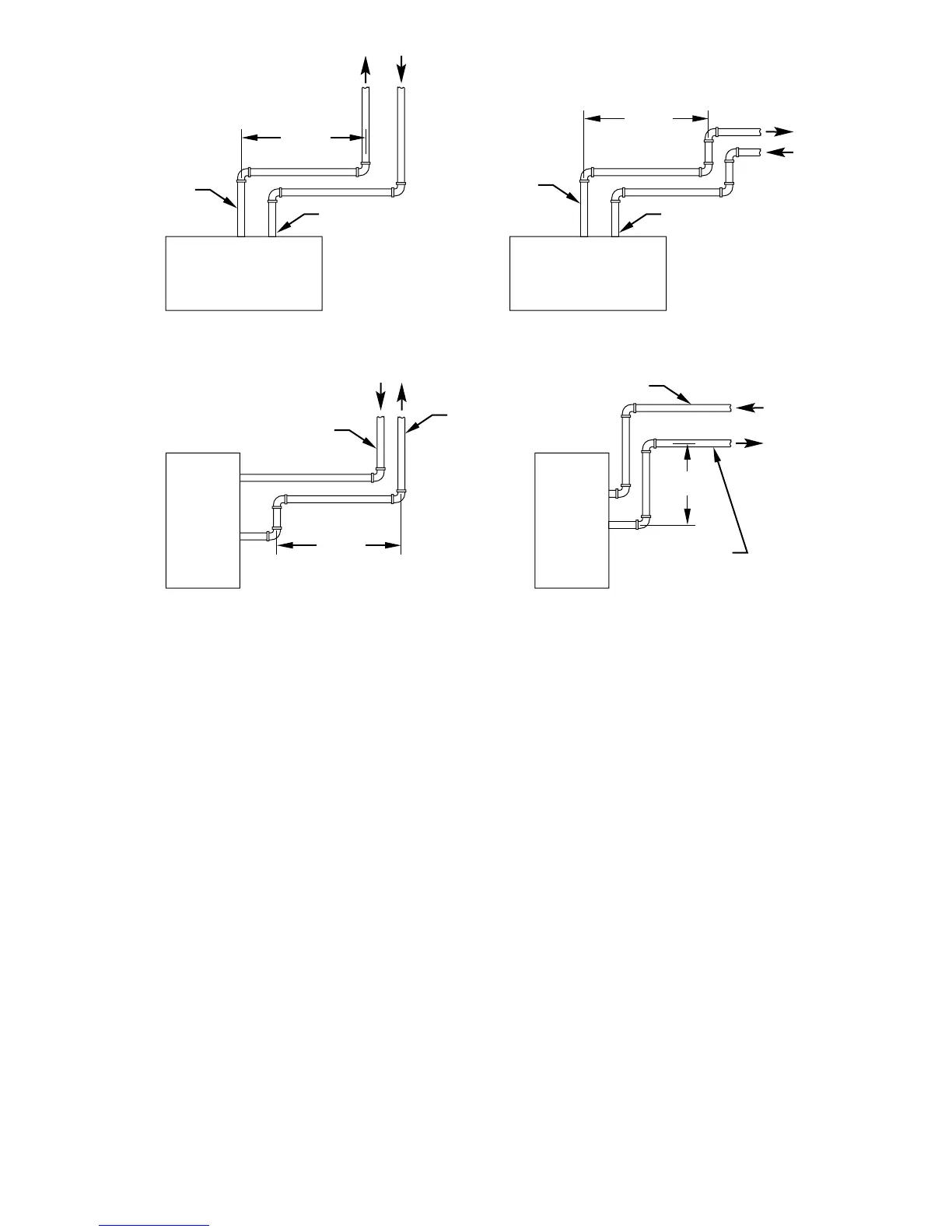
Fig. 35—Short Vent (5 to 8 ft) System
A96230
HORIZONTAL TO ROOF HORIZONTAL TO SIDEWALL
VERTICAL TO SIDEWALLVERTICAL TO ROOF
VENT PIPE
COMBUSTION-AIR PIPE COMBUSTION-AIR PIPE
VENT PIPE
COMBUSTION-AIR PIPE
VENT PIPE
COMBUSTION-AIR PIPE
VENT PIPE
12″ MIN
12″ MIN
12″ MIN
12″ MIN
NOTE: A 12 In. minimum offset pipe section is recommended with
short (5 to 8 ft) vent systems. This recommendation is to reduce
excessive condensate droplets from exiting the vent pipe.
—28—