15
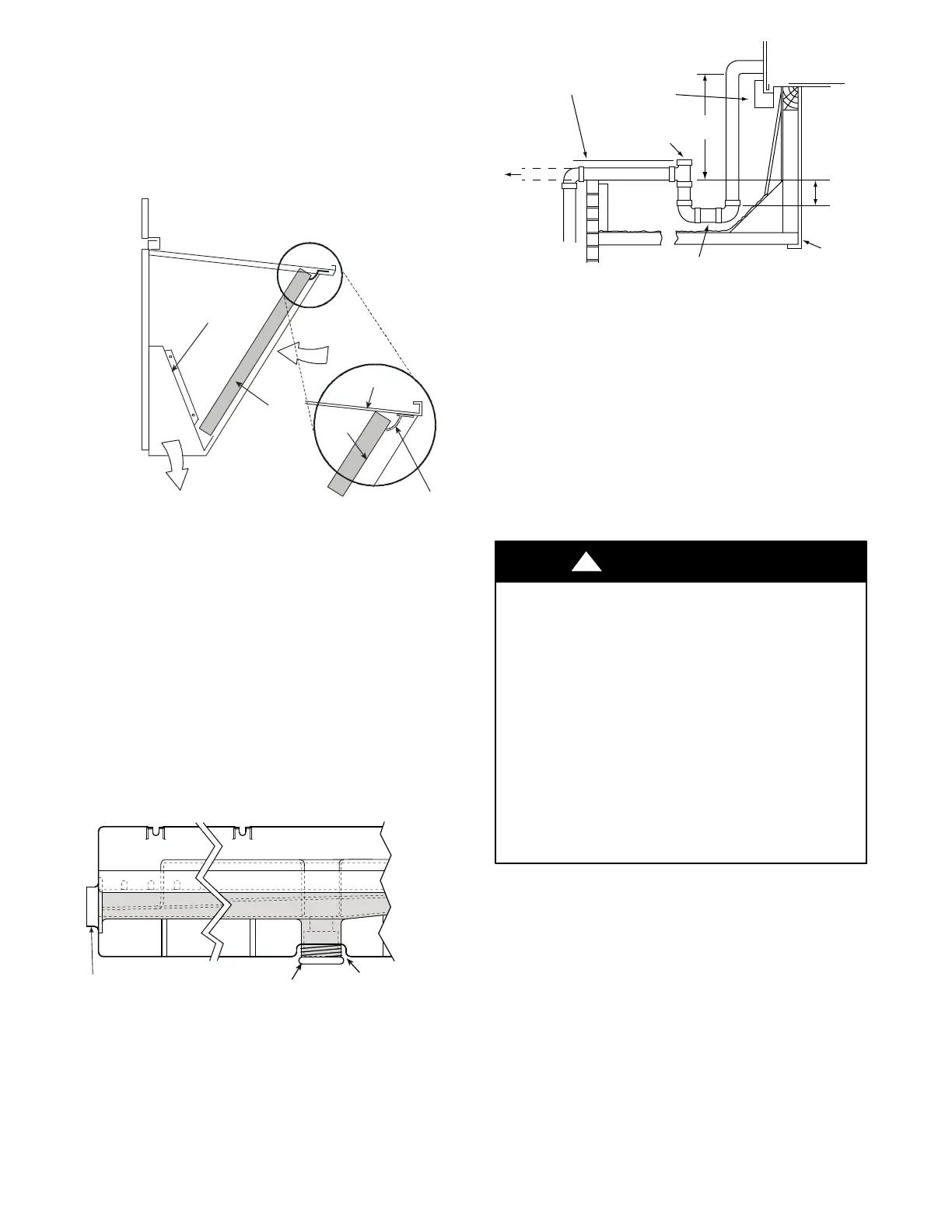
5. Open the filter clips which are located underneath the
hood top. Insert the aluminum filter into the bottom
filter rack (hood divider). Push the filter into position
past the open filter clips. Close the filter clips to lock
the filter into place. See Fig. 15.
6. Caulk the ends of the joint between the unit top panel
and the hood top.
7. Replace the filter access panel.
DIVIDER
BAROMETRIC
RELIEF
CLEANABLE
ALUMINUM
FILTER
FILTER
HOOD
FILTER
CLIP
OUTSIDE
AIR
C08634
Fig. 15 -- Economizer Filter Installation
Step 9 — Install External Condensate Trap
and Line
The unit has one
3
/
4
-in. condensate drain connect ion on
the end of the condensate pan and an alternate connection
on the bottom. See Fig. 16. Unit airflow configuration
does not determine which drain conne ction to use. Either
drain connection can be used with vertical or horizontal
applications.
To use the alternate bott om drain connection, remove the
red drain plug from the bottom connection (use a
1
/
2
-- i n .
squa re socket drive extension) and install it in the side
drain connection.
DRAIN
(FACTORY-INSTALLED)
PLUG
CONDENSATE PAN (SIDE VIEW)
STANDARD
SIDE DRAIN
ALTERNATE
BOTTOM DRAIN
C08021
Fig. 16 -- Condensate Drain Pan (Side View)
The pipi ng for the condensate drain and external trap can
be completed after the unit is in place. See Fig. 17.
NOTE: Trap should be deep enough to offset maximum unit static
difference. A 4 in. (102 mm) trap is recommended.
MINIMUM PITCH
1” (25mm) PER
10’ (3m) OF LINE
BASE RAIL
OPEN
VENT
TO ROOF
DRAIN
DRAIN PLUG
ROOF
CURB
SEE NOTE
3˝(76mm)
MIN
a50--- 9660
Fig. 17 -- Condensate Drain Piping Details
All units must have an external trap for condensate
drainage. Install a trap at least 4-in. (102 mm) deep and
protect against freeze-up. If drain line is installed
downstream from the external t rap, pitch the line away
from the unit at 1-in. per 10 ft (25 mm in 3 m) of run. Do
not use a pipe size smaller than the unit connection
(
3
/
4
-in.).
Step 10 — Make Electrical Connections
ELECTRICAL SHOCK HAZARD
Failure to follow this warning could result in personal
injury or death.
Do not use gas piping as an electrical ground. Unit
cabi net must have an uninterrupted, unbroken
electrical ground to minimize the possibility of
personal injury if an ele ctrical fa ult should occur. This
ground may consist of electrical wire connected to
unit ground lug in control compartment, or conduit
approved for electrical ground when installed in
accordance with NEC (National Electrical Code);
ANSI/NFPA 70, latest edition (in Canada, Canadian
Electrical Code CSA [Canadian Standards
Association] C22.1), and local electrical codes.
!
WARNING
NOTE: Check all factory and field electrical connections
for tightness. Field--supplied wiring shall conform with
the limitations of 63_F(33_C) rise.
Field Power Supply —
If equipped with optional Powered Convenience Outlet:
The power source leads to the convenience outlet’s
transformer primary are not factory connected. Installer
must connect these leads according to required operation
of the convenience outlet. If an always--energized
conveni ence outlet operation is de sired, conne ct the
source leads to the li ne side of the unit--mounted
disconnec t. (Check with local codes to ensure this met hod
is acceptable in your area.) If a de--energize via unit
disconnec t switch opera tion of the convenie nce outlet is
desired, connect the source lea ds to the load side of the
 Loading...