44
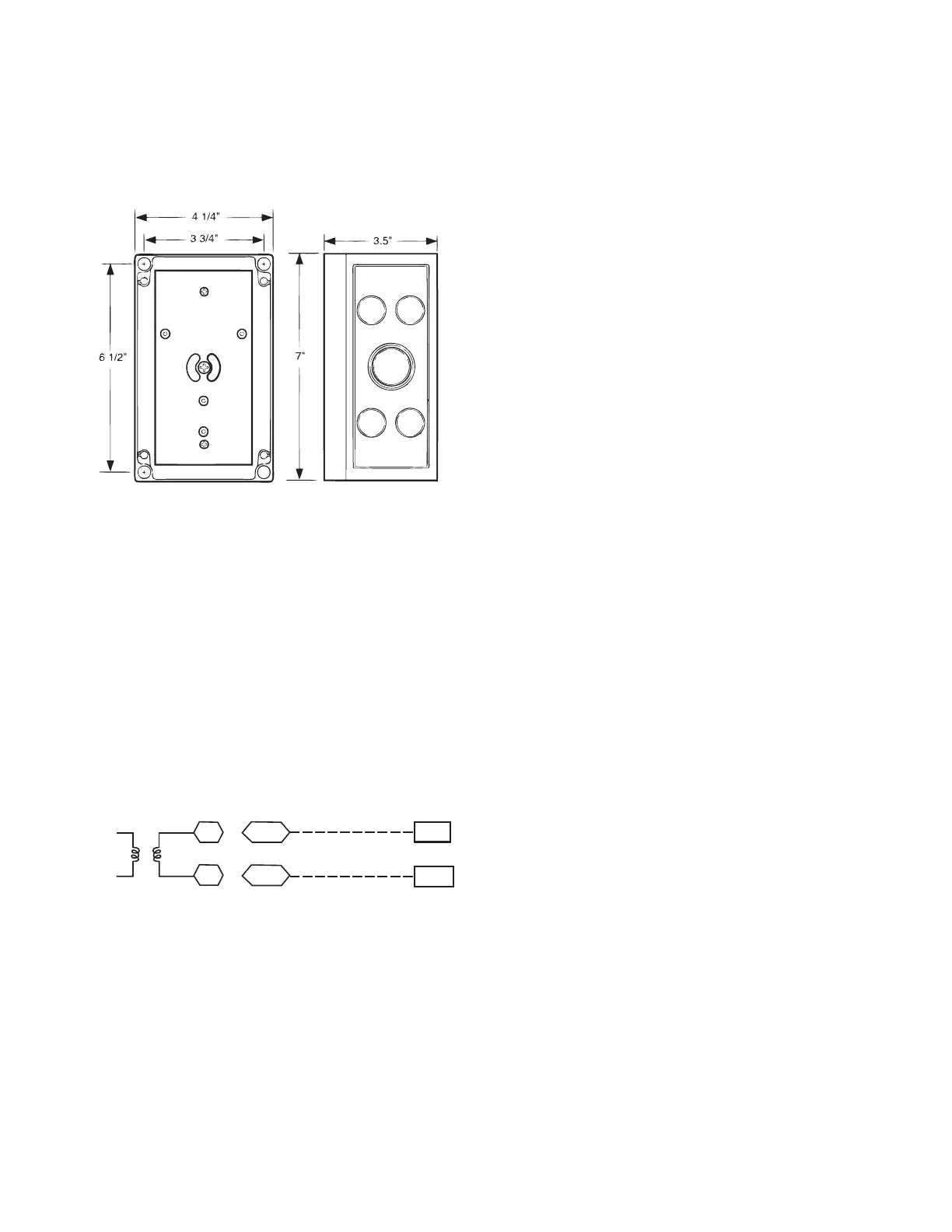
Outdoor Air Quality Sensor
(P/N 33ZCSENCO2 plus weatherproof enclosure) —
The outdoor air CO
2
sensor is designed to monitor carbon
dioxide (CO
2
) levels in the outside ventilation air and
interface with the ventilation damper in an HVAC system.
The OAQ sensor is packaged with an outdoor cover. See
Fig. 53. The outdoor air CO
2
sensor must be located in the
econom izer outside air hood.
COVER REMOVED SIDE VIEW
C07135
Fig. 53 -- Outdoor Air Quality Sensor Cover
Wiring the Outdoor Air CO
2
Sensor: A dedicated
power supply is required for this sensor. A two--wire cabl e
is required to wire the dedicated power supply for the
sensor. The two wires should be connected to the power
supply and terminals 1 and 2.
To connect the sensor to the control, identify the positive
(4 to 20 mA) and ground (SIG COM) terminals on the
OAQ sensor. See Fig. 51. Connect the 4 to 20 mA
terminal to the RTU Open controller at J4--5. Connect the
SIG COM terminal to the RTU Open controller at J4--6.
SEN
COM
J4-5
J4-6
OAQ Sensor/RH Sensor
24 VAC
C08463
Fig. 54 -- RTU Open Controller / Outdoor CO
2
Sensor
(33ZCSENCO2) Connections
Space Relative Humidity Sensor or Humidistat —
The Space Relative Humidity Sensor is not used with 549J
units at this time.
Smoke Detector/Fire Shutdown (FSD) —
On 549J units equipped with factory--installed Smoke
Detector(s), the smoke detector controller implements the
unit shutdown through its NC c ontact set connected to the
unit’s CTB input. T he FSD function is initiated via the
smoke detector’s Alarm NO contact set. The RTU Open
controller communicates the smoke detector’s tripped
status to the BAS building control. See Fig. 44 (Typical
RTU Open controller wiring diagram).
The F ire Shutdown Switch configuration,
MENU
Config
Inputs
input 5, identif ies the normally
open status of this input when there is no fire alarm.
Connecting Discrete Inputs —
Filter Status: The filter status accesso ry is a field--installed
access ory. This accessory detects plugged filters. When
inst alling this accessor y, the unit mus t be configu red for
filter status by setting MENU
Config
Inputs
input 3, 5,
8, or 9 to F ilter Status and normally open (N/O) or normally
closed (N/C). Input 8 or 9 is recommended for easy of
installatio n . Refer to Fig. 43 and Fig. 44 for wire
termination s at J5.
Fan Status : The fan status accesso ry is a field--installed
access ory. This accessory detects when the indoor fan is
blow in g air . When ins talling this accesso ry, the unit must be
config u red for fan status by settin g
MENU
Config
Inputs
input3,5,8,or9to F an Status
and normally open (N/O) or normally closed (N/C). Input 8
or 9 is recommended for easy of installation. Refer to Fig.
43 and Fig. 44 for wire termination s at J5.
Remote Occupancy: The remote occupancy accessory is
a field--installed accessory. This accessory overrides the
unoccupi ed mode and puts the unit in occupied mode.
When installing this accessory, the unit must be
configured for remote occupancy by setting
MENU
Config
Inputs
input3,5,8,or9to Remote
Occupancy a nd normally open (N/O) or normally closed
(N/C).
Also set MENU
Schedules
occupancy source to DI
on/off. Input 8 or 9 is recommended for ease of
installation. Refer to Fig. 43 and Table 23 for wire
terminations at J5.
Power Exhaust (output): The relay used by the RTU
Open controller board to control power exhaust is a dry
conta ct which means it does not have 24vac. This 24vac
must be connected to the relay to allow it to operate the
power exhaust relay in the PE accessory. A 24vac source
must be provided to J11--2 on the RTU Open controller
board. Thi s can be provided by the unit’s transformer from
various sources. The “R” terminal on the unit’s central
terminal board (CTB) is a logical source. Refer to Fig. 43
and Fig. 44 for wire terminations at J1 1.
 Loading...