23
Table 7 – Heater Model Number
Bare Heater Model Number C R H E A T E R 0 0 1 A/B 0 0
Heater Sales Package P/N
Includes:
Bare Heater
Carton and packing materials
Installation sheet
C R H E A T E R 1 0 1 A/B 0 0
Single Point Boxes and Supplementary Fuses —
When the un it MOC P device value exceed s 60--A,
unit--mounted supplementary fuses are required for each
heater circuit. These fuses are inclu ded in access o ry Single
Point Boxes, with power distribution and fuse blocks. The
single point box will be installed directly under the unit
control box, just to the left of the partition separating the
indoor section (with electric heaters) from the outdoor
section . The Sing le Po int Box has a hinged access cover. See
Fig. 35. The Single Point Box also includes pigtails to
complete the wiring between the Sin gle Point Box and the
unit’s main control box terminals . Refer to the accesso r y
heater and Single Point Box installation instructions for
details on tap connections.
A
L
LIE
D
P
A
M
O
DE
L
NO
.
ER
I
A
L
N
O.
C
O
R
P
.
O
D
2
2
.
2
3
1
2
3
ISTED
AI
R
NDITIONIN
G
UI
P
ACCES
S
346
N
.
P
/
N
2-
5
6
1
0
-
4
RE
V
1
1
1
3
2
1
2
3
CONTROL
BOX
BUSHING
SINGLE
POINT BOX
MOUNTING
SCREWS
FOAM
BUSHING
DRIP BOOT
BRACKET
MOUNTING
SCREWS
HEATER
RELAYS
POWER
WIRES
HEATER
MOUNTING
SCREWS
C14253
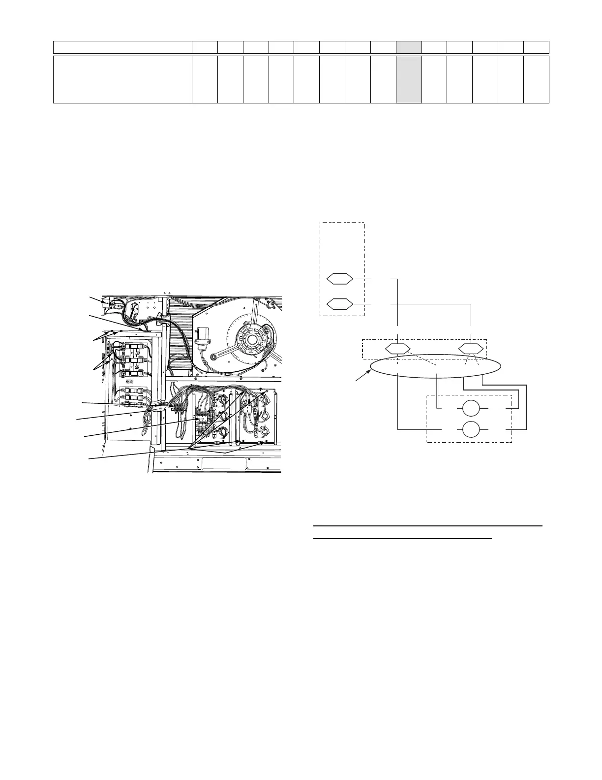
Fig. 35 -- Typical Single Point Installation
All fuses on 549J units are 60--A. (Note that all heaters are
qualified for use with a 60--A fuse, regardless of actual
heater ampacity, so only 60--A fuses are necessary.)
Single Point Boxes without Fuses —
Unit heater applications not requiring supplemental fuses
require a special Single Point Box without any fuses. The
accessory Single Point Boxes contain a set of power taps
and pigtails to complete the wiring between the Single
Point Box and the uni t’s main control box terminals. Refer
to accessory heater and Single Point Box installation
instructions for det ails on tap connections.
Low--Voltage Control Connections —
Run the low--voltage control lea ds from the heater
module(s) -- VIO and BRN (two of each if two modules
are install ed; identify for Module #1) -- to the 4--pole
terminal board TB4 located on the heater bulkhead to the
left of Heater #1. Connect the VIO leads from Heater #1
and Heater #2 to terminal TB4--1. Connect the BRN leads
to terminal TB4--3. See Fig. 36.
DEFROST
BOARD
ORN
BRN
Field
Connections
E-HEAT
P3-3
13
ORN BRN
VIO BRN BRN
VIO
TB4
VIO HR2
HR1
BRN
VIO BRN
Elec Htr
HR1: On Heater 1 in Position #1
HR2: On Heater 2 in Position #2 (if installed)
C09013
Fig. 36 -- Accessory Electric Heater Control
Connections
Variable Frequency Drive (VFD) 2--Speed Indoor
Fan Motor System
(Factory--Installed)
For details on operating 549J 2 stage cooling units
equippe d with the fact ory--installed Variable Frequenc y
Drive (VFD) 2--Speed Indoor Fan Motor System option,
refer to the Variable Frequency Drive (VFD) Installation,
Start--Up and Service Instructions.
 Loading...