1. See Fig. 10, 11, 12 and 13 for combustion air and vent pipe roof and sidewall termination. (Roof termination is preferred). Combustion air
and vent pipes must terminate together in same atmospheric pressure zone as shown. Construction through which vent and air intake pipes
may be installed is a maximum 24-in., minimum 1/4-in. thickness.
2. Combustion air and vent pipe fittings must conform to ANSI standards and ASTM standards D1784 (schedule-40 CPVC), D1785
(schedule-40 PVC), D2665 (PVC-DWV), D2241 (SDR-21 and SDR-26 PVC), D2661 (ABS-DWV), or F628 (schedule-40 ABS). Pipe
cement and primer must conform to ASTM standards D2564 (PVC) or D2235 (ABS). In Canada construct all combustion air and vent pipes
for this unit of CSA or ULC certified schedule-40 CPVC, schedule-40 PVC, PVC-DWV or ABS-DWV pipe and pipe cement.
3. SDR pipe is NOT approved in Canada.
4. Combustion air and vent piping connections on boiler are sized for 2-in. pipe (See Fig. 12). Any pipe size change (to 3-in.) must be made
outside of the boiler casing in vertical run of pipe to allow for proper drainage of vent condensate (See Fig. 13). Due to potential for flue
gas temperatures over 155°F, the first 5 ft of vent pipe must be CPVC, the remaining vent pipe can be PVC. If any elbows are employed
within the first 5 ft of vent, they must also be CPVC too The air intake pipe can be PVC. (See Fig. 14 and 15.)
NOTE: Two 2-1/2 foot long sections of 2–in. CPVC and 2–in. CPVC coupling are furnished with the boiler.
NOTE: The transition from 2-in. pipe to 3-in. pipe must be made in a vertical run. (See Fig. 13.)
5. Combustion air and vent piping lengths. (See Table 5.)
6. Combustion air and vent piping to be pitched back to boiler at minimum 1/4-in. per foot from intake and vent terminals so that all moisture
in combustion air and vent piping drains to boiler. Pipes must be pitched continuously with no sags or low spots where moisture can
accumulate and block the flow of air or flue gas. Combustion air and vent pipes must be airtight and watertight.
7. Consideration for the following should be used when determining an appropriate location for termination of combustion air and vent piping.
a. Comply with all clearances required as stated in Table 6 and Fig. 10, 11, 12 and 13.
b. Termination should be positioned where vent vapors will not damage plants/shrubs or air conditioning equipment.
c. Termination should be positioned so that it will not be affected by wind eddy, airborn leaves, snow, or allow recirculation of flue gases.
d. Termination should be positioned where it will not be damaged or subject to foreign objects, such as stones, balls, etc.
e. Termination should be positioned where vent vapors are not objectionable.
f. Put vent on a wall away from the prevailing winter wind. Locate or guard the vent to prevent accidental contact with people or pets.
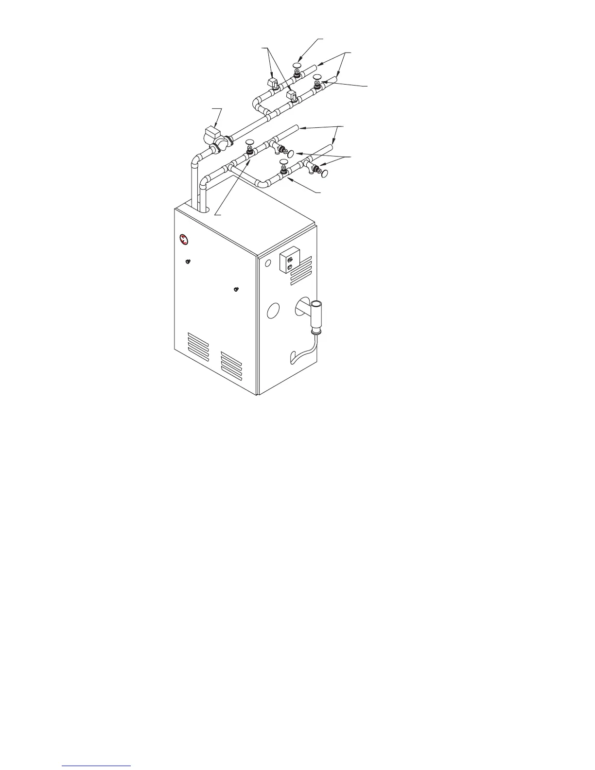
Fig. 4—Multizone Boiler Piping with Zone Valves
A99158
ZONE SERVICE
VALVE
ZONE
VALVE
ZONE SERVICE
VALVE
SUPPLY TO
ZONES
ZONE SERVICE
VALVE
RETURN FROM
ZONES
PURGE (DRAIN)
VALVES
ZONE SERVICE
VALVE
CIRCULATOR
—10—
→
→