A. Concentric Vent/Air Termination Kit
1. Determine location for termination. Consideration of the following should be made when determining an appropraite location for
termination kit.
a. Comply with all clearance requirements as stated in Procedure 4A.7.
b. Termination kit should be positioned so it will not damage plants/shrubs or air conditioning equipment.
c. Termination kit should be positioned so it will not be affected by wind eddy (such as inside building corners) or that may allow
recirculation of flue gases, airborne leaves, or light snow.
d. Termination kit should be positioned where it will not be damaged by or subjected to foreign objects, such as stones, balls, etc.
e. Termination kit should be positioned where vent vapors are not objectionable.
2. Cut one 4-in. diameter hole for 2-in. kit, or one 5-in. diameter hole for 3-in. kit.
3. Loosely assemble concentric vent/air termination components together using instructions in kit.
4. Slide assembled kit with rain shield REMOVED through hole.
a. Roof terminations—Locate assembly through roof to appropriate height as shown in Fig. 10.
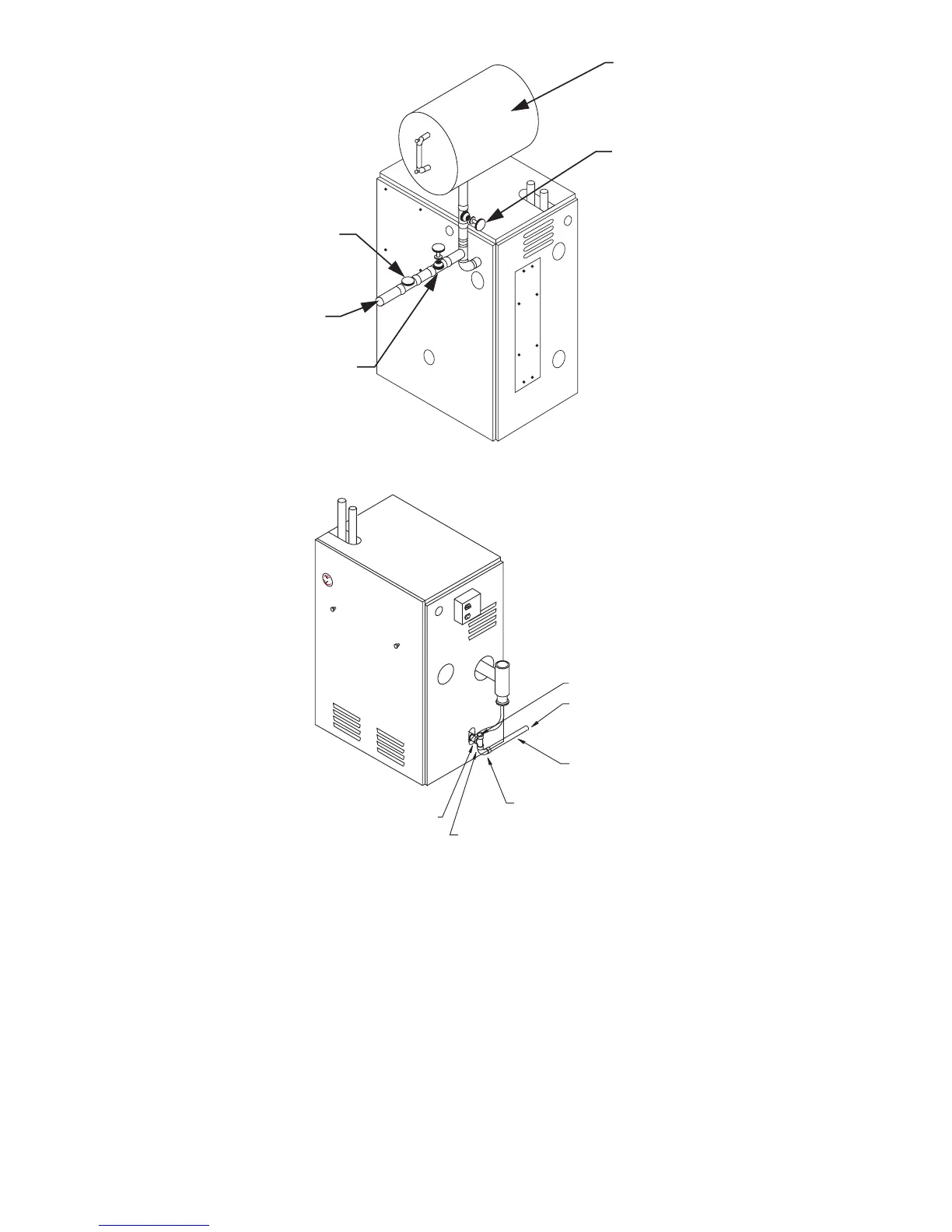
Fig. 8—Conventional (closed type) Expansion Tank Piping
A99162
CHECK AND PRESSURE
REDUCING VALVE
COLD WATER
FILL
MANUAL FILL
VALVE
EXPANSION TANK SERVICE
(GATE VALVE OR FULL PORT
BALL VALVE)
CLOSED TYPE
EXPANSION TANK
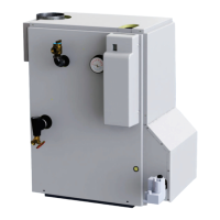
Fig. 9—Drain Piping
A99163
OPEN
DRAIN PIPE TO BE
PITCHED DOWN
TO FLOOR DRAIN
AT A MINIMUM 1/4”
PER FOOT
TO DRAIN
CONDENSATE
DRAIN
PVC TEE
1/2” SLIPx1/2”x1/2”NPT
FURNISHED IN PARTS BAG
THREADED NIPPLE (PVC)
(INSTALLED)
—13—