INSTALLATION
PROCEDURE 1—BEFORE INSTALLING THE BOILER
Complete all of the following prior to installing the boiler.
A. Codes
This boiler product is a gas fired direct vent condensing hot water boiler and must be installed in accordance with all applicable federal, state, and
local building codes including, but not limited to the following:
U.S.A.—Installation shall conform with NFPA-54/ANSI Z223.1.
Canada—Installation shall be in accordance with CAN/CGA B149.1 and .2 Installation Codes. Where required by the authority having
jurisdiction, the installation must conform to the A.S.M.E. Safety Code for Controls and Safety Devices for Automatically Fired Boilers, CSD-1.
The installation must conform to the requirements of the authority having jurisdiction or, in the absence of such requirements, to the NFGC, ANSI
Z223.1.
Installers—Follow local regulations with respect to installation of CO (CArbon Monoxide) Detectors. Follow maintenance recommendations in
this manual.
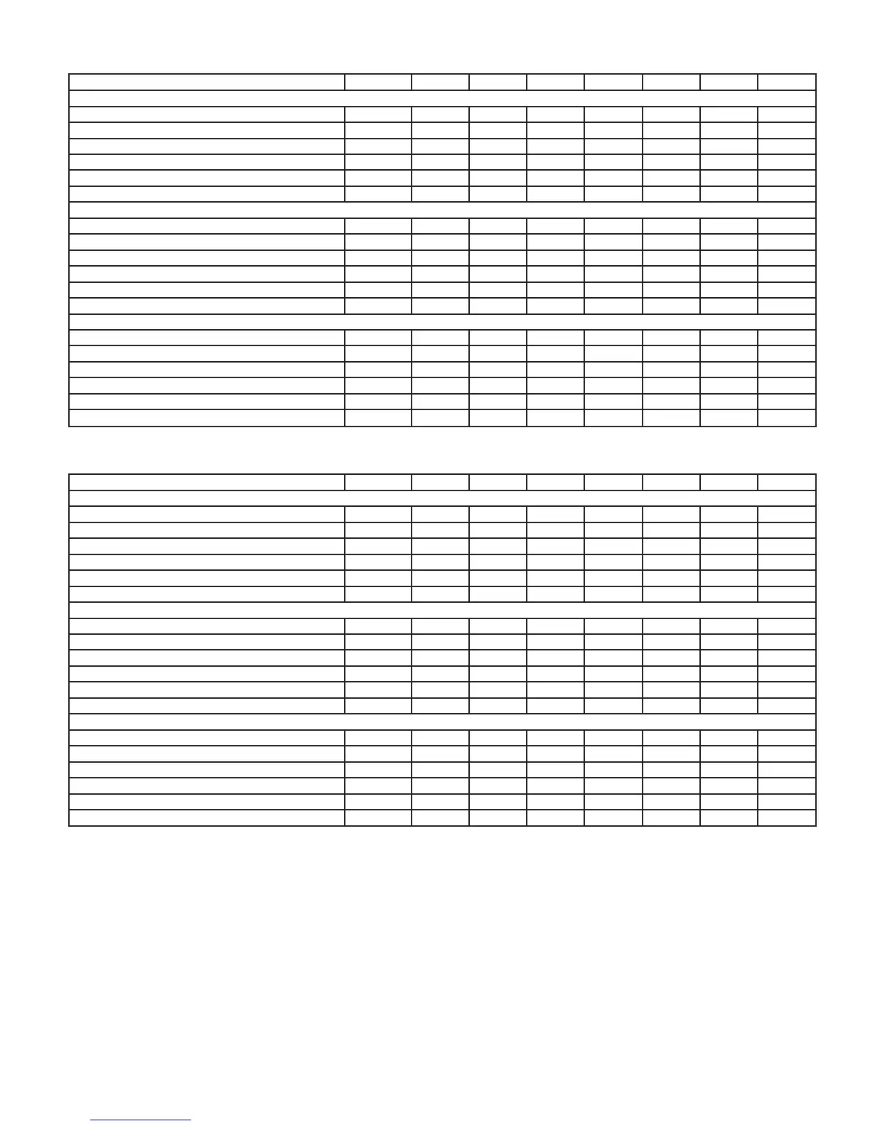
Table 2—Natural Gas High Altitude Ratings
ELEVATION (FT.) 0–2000 3000 4000 5000 6000 7000 7500 8500
BW9–50
Normal Input (MBH) 50.0 48.0 47.8 47.5 46.0 44.0 43.5 42.0
Heating Capacity (MBH) 45.0 43.2 43.0 42.8 41.4 39.6 39.2 37.8
Net I=B=R Rating (MBH) 39.0 37.4 37.3 37.1 35.9 34.3 34.0 32.8
Gas Orifice Drill Size .0615 .0615 .0615 .0615 .0615 .0615 .0615 .0615
Manifold Pressure (Inches Water Column) 2.5 2.7 3.0 3.2 3.1 3.0 2.8 2.7
Pressure Switch Setpoint (Inches Water Column) 1.55 1.55 1.55 1.55 1.55 1.55 1.55 1.55
BW9–75
Normal Input (MBH) 75.0 70.0 69.0 68.0 63.5 58.0 56.5 52.0
Heating Capacity (MBH) 68.0 63.0 62.1 61.2 57.2 52.2 50.9 46.8
Net I=B=R Rating (MBH) 58.9 54.6 53.8 53.0 49.6 45.2 44.1 40.6
Gas Orifice Drill Size .0760 .0760 .0760 .0760 .0760 .0760 .0760 .0760
Manifold Pressure (Inches Water Column) 2.5 2.7 2.8 3.0 2.8 2.6 2.3 2.1
Pressure Switch Setpoint (Inches Water Column) 1.35 1.35 1.35 1.35 1.35 1.35 1.35 1.35
BW9–100
Normal Input (MBH) 100.0 97.0 96.0 95.0 90.0 84.0 82.0 76.0
Heating Capacity (MBH) 90.0 87.3 86.4 85.5 81.0 75.6 73.8 68.4
Net I=B=R Rating (MBH) 78.0 75.7 74.9 74.1 70.2 65.5 64.0 59.3
Gas Orifice Drill Size .0860 .0860 .0860 .0860 .0860 .0860 .0860 .0860
Manifold Pressure (Inches Water Column) 2.5 2.9 3.3 3.7 3.4 3.2 2.9 2.6
Pressure Switch Setpoint (Inches Water Column) 1.00 1.00 1.00 1.00 1.00 1.00 1.00 1.00
Table 3—Propane Gas High Altitude Ratings
ELEVATION (FT.) 0–2000 3000 4000 5000 6000 7000 7500 8500
BW9–50
Normal Input (MBH) 50.0 49.0 49.0 49.0 48.0 46.5 46.0 44.0
Heating Capacity (MBH) 45.0 44.1 44.1 44.1 43.2 41.9 41.4 39.6
Net I=B=R Rating (MBH) 39.0 38.2 38.2 38.2 37.4 36.3 35.9 34.3
Gas Orifice Drill Size .0492 .0492 .0492 .0492 .0492 .0492 .0492 .0492
Manifold Pressure (Inches Water Column) 2.5 2.8 3.1 3.4 3.4 3.5 3.5 3.5
Pressure Switch Setpoint (Inches Water Column) 1.55 1.55 1.55 1.55 1.55 1.55 1.55 1.55
BW9–75
Normal Input (MBH) 75.0 70.0 69.0 67.0 66.0 64.5 64.0 62.0
Heating Capacity (MBH) 68.0 63.0 62.1 60.3 59.4 58.1 57.6 55.8
Net I=B=R Rating (MBH) 58.9 54.6 53.8 52.3 51.5 50.4 49.9 48.4
Gas Orifice Drill Size .0605 .0605 .0605 .0605 .0605 .0605 .0605 .0605
Manifold Pressure (Inches Water Column) 2.5 2.4 2.3 2.2 2.2 2.2 2.3 2.3
Pressure Switch Setpoint (Inches Water Column) 1.35 1.35 1.35 1.35 1.35 1.35 1.35 1.35
BW9–100
Normal Input (MBH) 100.0 95.0 94.0 92.0 92.0 91.5 91.5 91.0
Heating Capacity (MBH) 90.0 85.5 84.6 82.8 82.8 82.4 82.4 81.9
Net I=B=R Rating (MBH) 78.0 74.1 73.3 71.8 71.8 71.4 71.4 71.0
Gas Orifice Drill Size .0670 .0670 .0670 .0670 .0670 .0670 .0670 .0670
Manifold Pressure (Inches Water Column) 2.5 2.7 2.9 3.1 3.2 3.3 3.4 3.5
Pressure Switch Setpoint (Inches Water Column) 1.00 1.00 1.00 1.00 1.00 1.00 1.00 1.00
—5—
→
→
→