g. Terminate the vent above normal snowline. Avoid locations where snow may drift and block the vent. Ice or snow may cause the boiler
to shut down if the vent becomes obstructed.
h. Under certain conditions, flue gas will condense, forming moisture, and may be corrosive. In such cases, steps should be taken to prevent
building materials at the vent from being damaged by exhaust of flue gas.
8. The venting system shall terminate at least 3 ft above any forced air inlet (except the boiler’s combustion air inlet) within 10 ft. The venting
system shall terminate at least 12-in. from any air opening into any building. The bottom of the vent shall be located at least 12-in. above
grade or anticipated snowline. Termination of the vent shall be not less than 7 ft above an adjacent public walkway. The vent terminal shall
not be installed closer than 3 ft from the inside corner of an L shaped structure. Termination of the vent should be kept at least 3 ft away
from vegetation. The venting system shall terminate at least 4 ft horizontally from, and in no case above or below, unless a 4 foot horizontal
distance is maintained, from electric meters, gas meters, regulators, and relief equipment. Maintain 3 ft horizontal distance from dryer vents.
B. Installation
1. Attach combustion air intake piping to factory supplied Fernco 2–in. rubber coupling on mixer. Attach vent piping to factory supplied 2–in.
CPVC vent tee on draft inducer outlet.
NOTE: All pipe joints are to be water tight.
2. Working from the boiler to the outside, cut pipe to required length(s).
3. Deburr inside and outside of pipe.
4. Chamfer outside edge of pipe for better distribution of primer and cement.
5. Clean and dry all surfaces to be joined.
6. Check dry fit of pipe and mark insertion depth on pipe.
NOTE: It is recommended that all pipes be cut, prepared, and pre-assembled before permanently cementing any joint.
7. After pipes have been cut and pre-assembled, apply cement primer to pipe fitting socket and end of pipe to insertion mark. Quickly apply
approved cement to end of pipe and fitting socket (over primer). Apply cement in light, uniform coat on the inside of socket to prevent
buildup of excess cement. Apply second coat.
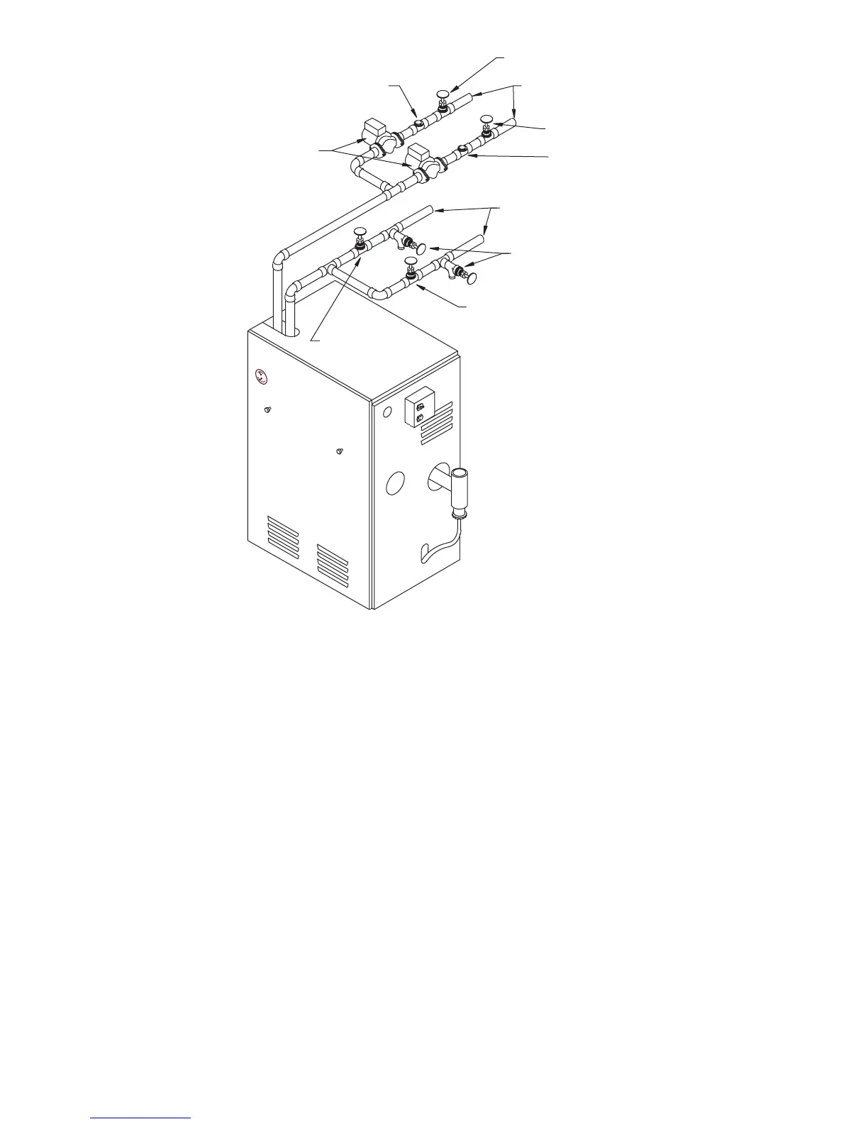
Fig. 5—Multizone Boiler Piping with Circulators
A99159
FLOW CHECK
VALVE
ZONE SERVICE
VALVE
SUPPLY TO
ZONE
ZONE SERVICE
VALVE
FLOW CHECK
VALVE
RETURN FROM
ZONES
PURGE (DRAIN)
VALVES
ZONE SERVICE
VALVE
ZONE SERVICE
VALVE
CIRCULATORS
—11—