j. Restore electrical power and gas supply to unit.
2. Check that boiler area is free from combustible materials, gasoline, and other flammable vapors and liquids.
WARNING: Keep boiler area clean of debris and free of flammable and combustible materials, vapors, and liquids.
Failure to follow this warning could result in fire, property damage, personal injury, or death.
3. Circulator pump and blower motor furnished with boiler are permanently lubricated from the factory and require no further lubrication.
Additional or non-factory supplied pumps and/or motors should be lubricated according to the pump and/or motor manufacturer’s
instruction.
PROCEDURE 2—DAILY DURING HEATING SEASON
WARNING: Disconnect electrical power to unit. Turn off gas supply to unit at the gas supply shutoff. Failure to do so
could result in fire, personal injury, property damage, or death.
1. Check for and remove any obstruction to the flow of combustion air or venting of flue gases.
2. Check that boiler area is free from combustible materials, gasoline, and other flammable vapors and liquids.
WARNING: Keep boiler area clean of debris and free of flammable and combustible materials, vapors, and liquids.
Failure to follow this warning could result in fire, property damage, personal injury, or death.
PROCEDURE 3—MONTHLY DURING HEATING SEASON
WARNING: Disconnect electrical power to unit. Turn off gas supply to unit at the gas supply shutoff. Failure to do so
could result in fire, personal injury, property damage, or death.
1. Remove jacket front and top panels and check for piping leaks around relief valve and other fittings. If found, contact a qualified service
agency to repair.
WARNING: DO NOT use stop leak compounds. Failure to do so could result in fire, personal injury, property damage,
or death.
2. Test relief valve. Refer to valve manufacturers instructions packaged with relief valve.
3. Visually inspect venting and air intake system for proper function, deterioration, or leakage. If the vent or air intake show any signs of
deterioration or leakage, contact a qualified service agency to repair or replace them immediately and to insure proper reassembly and
resealing of the vent and air intake system.
4. Visually inspect the clear vinyl condensate lines and the PVC condensate drain pipe for proper operation, leakage, and deterioration. If the
condensate lines or drain pipe show any signs of blockage, leakage, or deterioration contact a qualified service agency to clean, repair, or
replace them immediately.
5. Check air vent(s) for leakage.
6. Check the air baffle located inside 1-1/2-in. X 2-in. flexible coupling, clean it if necessary and make sure to put it back. Refer to repair parts
diagram, mixer and pressure switch assembly.
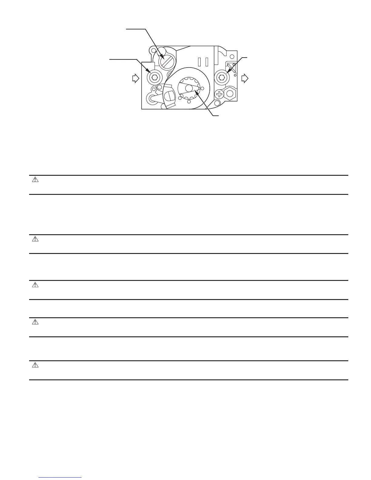
Fig. 23—Gas Valve
A00312
GAS CONTROL
KNOB SHOWN
IN "ON" POSITION
GAS
INLET
OFF
ON
A95154
OUTLET
PRESSURE
TAP
PRESSURE
REGULATOR
ADJUSTMENT
(UNDER CAP SCREW)
OUTLET
PRESSURE
TAP
GAS
INLET
—29—