Remove the 1/8-in. plug from the outlet pressure tap. Install the appropriate barbed fitting into the outlet pressure tap and connect the pressure
side of the guage or manometer to the barbed fitting.
Refer to “Measure the Gas Input Rate” in these instructions when reading manifold pressure.
When measurement is complete, disconnect gauge or manometer and remove barbed fitting. Reinstall 1/8-in. plug using the appropriate pipe
sealant for use with natural gas and propane.
F. Test High Limit Control and Adjust
While burner is operating, move indicator on high limit control below actual boiler water temperature. Burner should go off while circulator
continues to operate. Raise limit setting above boiler water temperature and burner should reignite after prepurge and igniter warm-up period. Set
the high limit control to the design temperature requirements of the system. Maximum high limit setting is 200°F. Minimum high limit setting is
100°F.
G. Test Other Safety Controls
If the boiler is equipped with a low water cut-off, a manual reset high limit, or additional safety controls, test for operation as outlined by the control
manufacturer. Burner should be operating and should go off when controls are tested. When safety controls are restored, burner should reignite.
H. Set Thermostat Heat Anticipator (If Used) and Verify Thermostat Operation
For a single thermostat connected to the yellow thermostat lead wires in the furnished field wiring junction box, the heat anticipator should be set
at 0.7 amps. For other wiring configurations, refer to the instructions provided by the thermostat manufacturer regarding adjustment of heat
anticipator. Cycle boiler with thermostat. Raise the thermostat to the highest setting and verify boiler goes through normal start up cycle. Lower
thermostat to lowest setting and verify boiler goes off.
I. Measure the Gas Input Rate
NATURAL GAS
Correct input rate is essential for proper and efficient operation of the burner and boiler.
1. Determine elevation at installation site.
2. See Table 2 to determine the correct input rate for local elevation.
3. Obtain yearly average heating value of local gas supply from gas utility. At sea level elevation, it should be approximately 1000 Btu’s per
standard cubic foot (for natural gas only).
4. Operate boiler for 5 minutes.
5. Turn off all other gas appliances, extinguishing standing pilots where applicable.
6. At gas meter, measure time in sec required to use one cubic foot of gas (for natural gas only).
7. Calculate input rate for natural gas according to the following formula:
8. Measured input rate should be within +/- 2 percent of the input rating from step 2. If within 2 percent, go to step 9. If not, adjustment is
required, proceed as follows:
a. Turn boiler off.
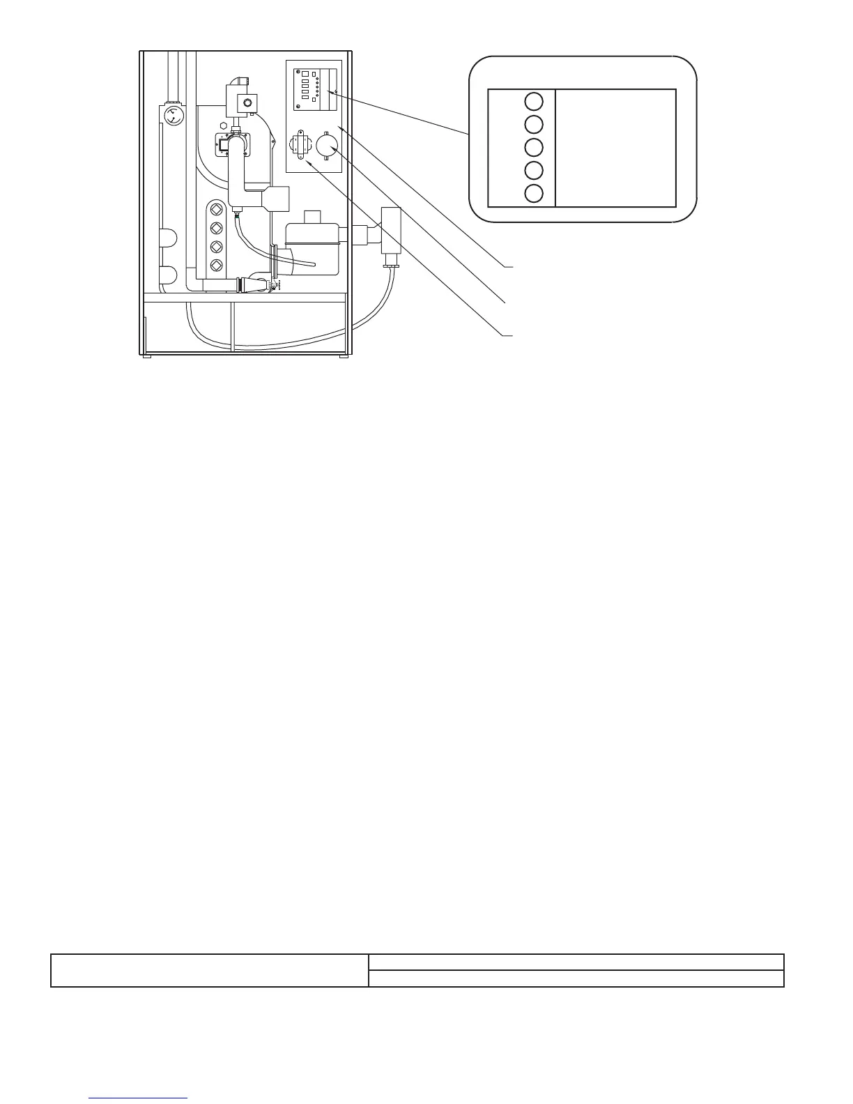
Fig. 21—Indicator Lamps
A99170
DIAGNOSTIC INDICATOR LAMPS
A POWER
B PURGE
C IGNITER
D VALVE
E FLAME
CONTROL PANEL
AIR PRESSURE SWITCH
TRANSFORMER
BTUH INPUT RATE =
3600 X HEATING VALUE FROM STEP 3
time for step 6
—26—
→
→
→