A. Connecting the Gas Piping
Refer to Fig.16 for the general layout at the boiler. It shows the basic fittings you will need. The gas line enters the boiler from the right side jacket
panel. The boiler may receive the gas supply pipe through the left side, or rear jacket panel by relocating the gas valve connector and pipe assembly.
The boiler is equipped with a 1/2-in. NPT connection on the gas valve for supply piping. The following rules apply:
1. Use only those piping materials and joining methods listed as acceptable by the authority having jurisdiction, or in the absence of such
requirements, by the National Fuel Gas Code, NFPA-54-2002/ANSI Z223.1-2002. In Canada, follow the CAN/CGA B149.1 and .2
installation Codes for Gas Burning Appliances and Equipment.
2. Use pipe joint compound suitable for propane gas on male threads only.
3. Use ground joint unions.
4. Install a sediment trap upstream of gas controls.
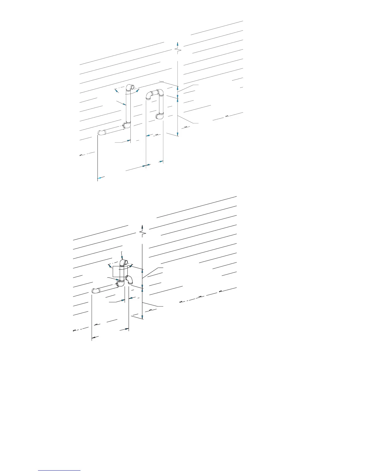
Fig. 13—Sidewall Vent/Intake Terminations
A99165
OVERHANG
12” MINIMUM
12” SEPARATION
BETWEEN BOTTOM OF
COMBUSTION AIR INTAKE
AND BOTTOM OF VENT
MAINTAIN 12” MINIMUM CLEARANCE
ABOVE HIGHEST ANTICIPATED SNOW
LEVEL OR GRADE
15”
MAXIMUM
18”
MAXIMUM
3”
MAXIMUM
SEPARATION
VENT
90°
LESS THAN 12” CLEARANCE
OVERHANG
12” SEPARATION
BETWEEN BOTTOM OF
COMBUSTION AIR INTAKE
AND BOTTOM OF VENT
MAINTAIN 12” MINIMUM CLEARANCE
ABOVE HIGHEST ANTICIPATED
SNOW LEVEL OR GRADE
12” MINIMUM
VENT
18”
MAXIMUM
3”
MAXIMUM
SEPARATION
90°
BRACKET
12” OR MORE CLEARANCE
—16—