PROCEDURE 6—GAS SUPPLY PIPING
The gas pipe to your boiler must be the correct size for the length of run and for the total BTU per hour input of all gas utilization equipment
connected to it. See Table 7 for the proper size. Be sure your gas line complies with local codes and gas company requirements.
The boiler and its individual shutoff valve must be disconnected from the gas supply piping system during any pressure testing of that system at
test pressures in excess of 1/2 psig (3.5kPa).
The boiler must be isolated from the gas supply piping system by closing its individual manual shutoff valve during any pressure testing of the
gas supply piping system at test pressures equal to or less than 1/2 psig (3.5kPa).
The MAXIMUM GAS SUPPLY PRESSURE for NATURAL gas is 11.0-in.w.c. The MINIMUM GAS SUPPLY PRESSURE for NATURAL
gas is 5.0-in. w.c. (See Table 8.)
The MAXIMUM GAS SUPPLY PRESSURE for PROPANE is 14.0-in.w.c. The MINIMUM GAS SUPPLY PRESSURE for PROPANE is
10.0-in.w.c. (See Table 8.)
NOTE: Gas pressures at or below the minimum gas supply pressures may result in nusiance ignition lock-outs or poor operational performance.
Table 6—Combustion-Air and Vent Pipe
Termination Clearances
LOCATION
CLEARANCE (FT)
U.S.A. Canada
Above grade level or above anticipated
snow depth
11†
Dryer/Water heater vent See Note 5 See Note 5
From plumbing vent stack 33
From any mechanical fresh air intake See Note 4 See Note 6
For furnaces with an input capacity
100,000 Btuh or less—from any non-
mechanical air supply (windows or doors
which can be opened) or combustion-air
opening
11
For furnaces with an input capacity
greater than 100,000 Btuh–from any non-
mechanical air supply (windows or doors
which can be opened) or combustion-air
opening
13
From service regulator vent, electric and
gas meters, and relief equipment
See Note 6 See Note 6
Above grade when adjacent to public
walkway
See Note 3 See Note 3
† 18 in. above roof surface in Canada.
NOTES: 1. If installing 2 adjacent Furnaces, refer to Multiventing and Vent
Terminations section for proper vent configurations.
2. When locating combustion-air and vent terminations, consideration must be
given to prevailing winds, location, and other conditions which may cause
recirculation of the appliance’s own flue products or the flue products of
adjacent vents. Recirculation can cause poor combustion, inlet condensate
problems, and accelerated corrosion of heat exchangers.
3. Vent termination can not terminate less than 2 ft horizontal and 7 ft above
public walkway or where condensate vapor or droplets may be a hazard.
4. Vent termination must be at least 3 feet above any forced draft inlets within 10 feet horizontal. Vent termination must be at least 3 feet horizontal from other direct vent
appliances intake unless otherwise specified by manufacturer.
5. 3 ft radius of furnace air-intake terminal and 1 ft horizontally from vertical centerline of furnace air-intake terminal.
6. Above a meter/regulator within 3 feet horizontally of vertical centerline of meter/regulator vent outlet to a maximum vertical distance of 15 ft.
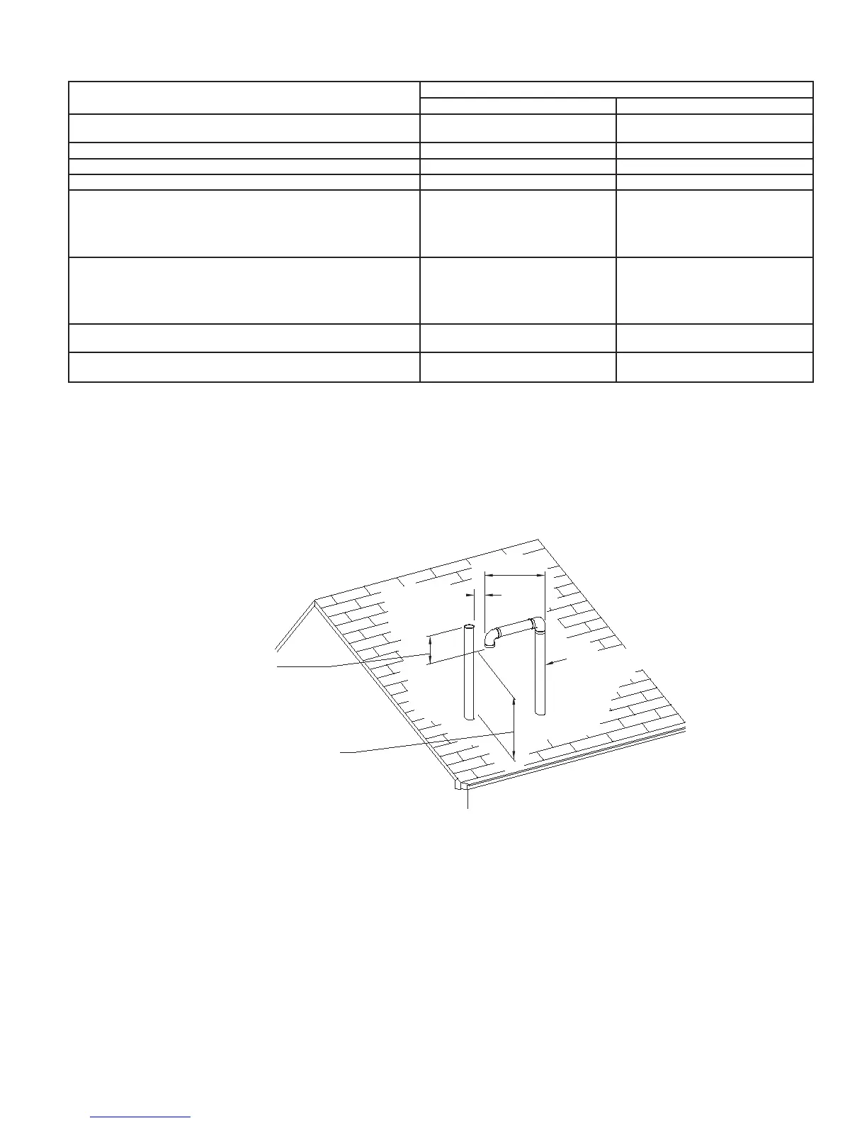
Fig. 12—Roof Vent/Intake Terminations
A99164
12” MINIMUM
VERTICAL SEPARATION
BETWEEN COMBUSTION
AIR INTAKE AND VENT
MAINTAIN 12” MINIMUM
CLEARANCE ABOVE HIGHEST
ANTICIPATED SNOW LEVEL
COMBUSTION
AIR
15” MAXIMUM
3” MAXIMUM
SEPARATION
—15—
→
→
→