506 01 2303 01 11
Specifications are subject to change without notice.
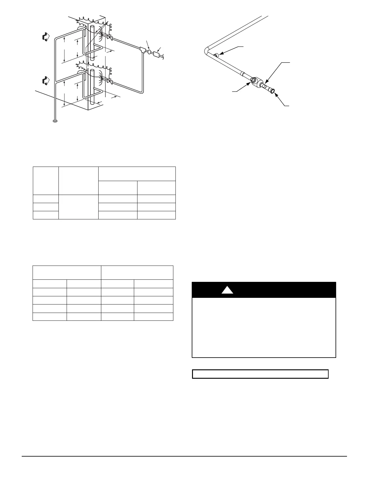
LEGEND
TXV — Thermostatic Expansion Valve
INDOOR
COIL CKT 2
AIRFLOW
INDOOR
COIL CKT 1
AIRFLOW
15 DIAMS
MIN
10
DIAMS
8 DIAMS
MIN
TXV
SENSING
BULB
EQUALIZER LINE
SIGHT GLASS
LOCATION
TXV
CKT 2
FILTER DRIE
LOCATION
TXV
SENSING
BULB
TXV
CKT 1
8 DIAMS
MIN
15 DIAMS
MIN
10
DIAMS
C11037
Fig. 6 -- Location of Sight Glass(es) and Filter Driers
(typical CHS size 121)
Table 6 – Minimum Outdoor Air Operating Temperature
UNI T
%
COMPRESSOR
CAPACITY
MINIMUM OUTDOOR
TEMP — F (C)*
Standard Unit
Head Pressure
Control
†
CHS072
100
35 (1.7) –20 (–28.9)
CHS091
35 (1.7) –20 (–28.9)
CHS121 35 (1.7) –20 (–28.9)
* Applies to Cooling mode of operation only.
† Wind baffles (field-supplied and field-installed) are recommended for all
units with low ambient head pressure control. Refer to Low Ambient
Control Installation Instructions (shipped with accessory) for details.
Table 7 – Insulation for Vapor Line Exposed
to Outdoor Conditions
LENGTH OF EXPOSED
VAPOR LINE*
INSULATION THICKNESS
†
ft m in. mm
10 3
3
/
8
10
25 8
1
/
2
13
35 11
3
/
4
19
50 15
3
/
4
19
* Recommended vapor line insulation for piping exposed to outdoor
conditions to prevent loss of heating during heating cycle. When vapor
line goes through interior spaces, insulation should be selected to pre-
vent condensation on cooling cycle. Heating capacity should be re-
duced 1000 Btuh (295 W) if over 35 ft (11 m) of vapor line with
3
/
4
in. (19
mm) insulation is exposed to outdoor conditions.
† Closed cell foam insulation with a thermal conductivity of: 0.28 Btu S
in./ft
2
S h S F (0.04 W/m S C).
Make Piping Connections —
Piping connec tions a t the CHS unit are ball valves with
stub tube extensions. Do not open the unit service val ves
until all interconnecting tube brazing as been completed.
The stub tube connections include
1
/
4
-in SAE service fittin gs
with Schrader valve cores (see Fig. 7). Before making any
brazed connections to the unit service valves, remove both
Schrader valve caps and cores and save for re-installation.
Con nect a s ou r ce for nitrogen to one of thes e s er vice fittings
during tube brazing to prevent the formation of copper
oxides inside the tub es at brazed joints.
Factory
High-Flow
Access Port
Service Valve
with Stem Cap
Field Service
Access Port
(Schrader core)
Sweat
Connection
C150028
Fig. 7 -- Typical Piping Connection Assembly
When connecting the field tubing to the CHS service
valves, wrap the valve s in wet rags to prevent overheating
Pressure-test all joints from outdoor unit connecti ons over
to the indoor coil, using nit rogen as pressure and with
soap-and-bubbles.
When pressure-testing is completed, remove the nitrogen
source at the outdoor unit service valves and re-install the
two Schrader valve cores. Torque the cores to 2-3 in-lbs
(23-34 N-cm).
Where vapor line is e xposed to outdoor air, line must be
insulated. See Table 7 for insulation requirements.
Evacuation/Dehydration —
Evac uate and dehydrate the connec ted refrigeration
system(s) (excluding the CHS unit) to 500 microns using a
two-stage vacuum pump attached to the service ports
outside the CHS service valves, following description in
GTAC II, Module 4, System Dehydration.
UNIT OPERATION AND SAFETY HAZARD
Failure to follow this warning c ould cause personal
injury, death and/or equipment damage.
R--410A refrigerant systems operate at higher
pressures than standard R--22 systems. Do not use
R--22 service equipment or components on R--410A
refrigerant equipment.
!
WARNING
IMPORTANT: Charge in Cooling mode only!
Preliminary Charge —
Before starting the unit, charge R-410A liquid refrige rant
into the high side of each CHS c ircuit through the liquid
service valve(s). The amount of refrigerant added must be
at least 80% of the operating charge listed in Table 2 for
LINEAR line length LESS the factory charge quantity (if
factory shipping charge has not been removed). See the
following example.