8 506 01 2303 01
Specifications are subject to change without notice.
Do not install the outdoor unit in an area where fresh air
supply to the outdoor coil may be restricted or when
recirculat ion from the condenser fan discharge is possible.
Do not loca te the unit in a well or next to high walls.
Evaluate the path and required line length for
interconnect ing refrigeration piping, includi ng vapor riser
requirements and liquid line lift; a heat pump system will
have one of each type in opposite modes. Relocate
sections to minimize the length of interconnecting tubing.
DO NOT BURY REFRIGERATION LINES.
Although unit is weatherproof, avoid locations that permit
water from higher leve l runoff and overhangs to fall onto
the unit.
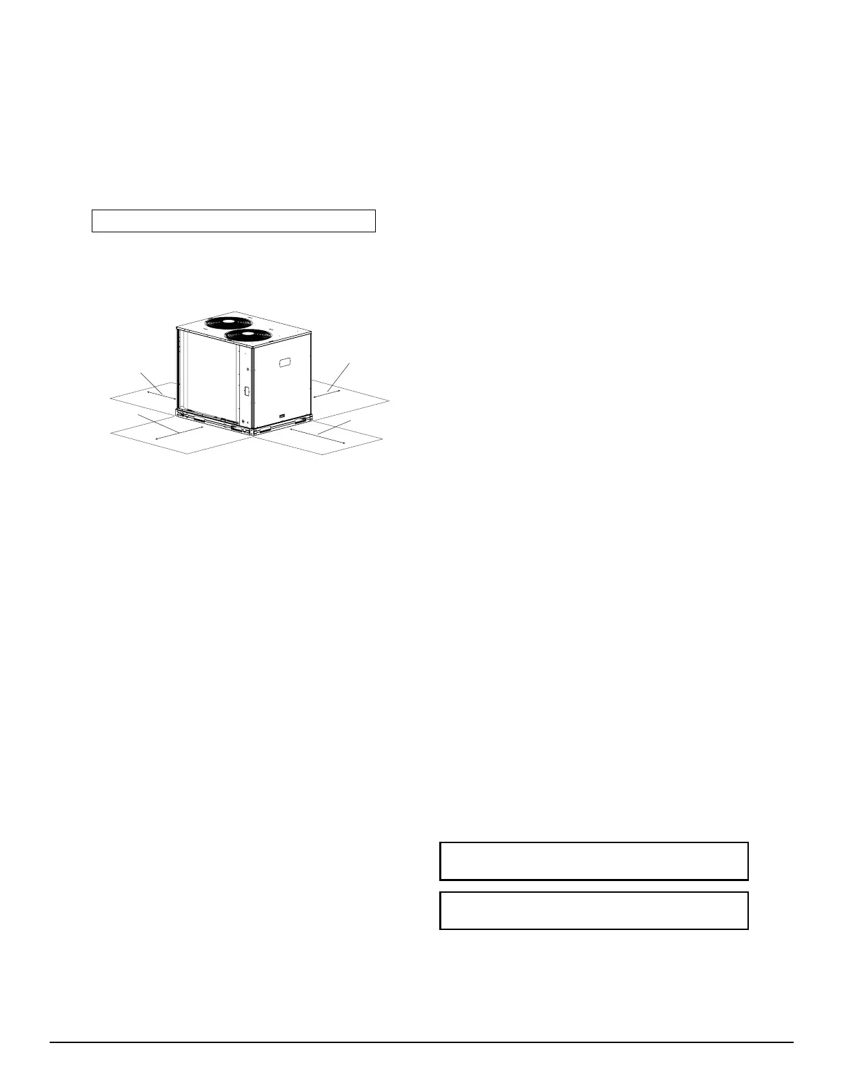
REAR:
Min 18” (457 mm)
requried for service
Note: Observe requirements for 39” (914 mm) operating clearance
on either Left or Rear coil opening.
RIGHT:
Min 18” (457 mm)
requried for service
LEFT:
Min 18” (457 mm)
requried for service
FRONT:
42” (1067 mm)
C11035
Fig. 4 -- Service Clearance Dimensional Drawing
Step 2 — Complete Pr e-Installation Checks
Ch eck Unit Electric Ch aracteris tic —
Confirm before install ation of unit that voltage, amperage
and circuit protection requirements listed on unit data
plate agree with power supply provided.
Un--crate Unit —
Remove unit pa ckaging except for the top skid assembly,
which should be left in place until after the unit is rigged
into its final location.
Inspect Shipment —
File a claim with shipping company if the shipment is
dama ged or incomplete.
Consider System Requirements —
S Consult local building codes and National Electrical
Code (NEC, U.S.A.) for special installation
requirements.
S Allow sufficient space for airflow clearance, wiring,
refrigerant piping, and servicing unit. See Fig. 1 for unit
dimensions and wei ght distribution data.
S Locate the unit so that the outdoor coil (condenser)
airflow is unrestricted on all sides and above.
S The unit may be mounted on a level pad directly on the
base channels or mounted on raised pads at support
points. See Tables 1A and 1B for unit operating
weights. See Fig. 1 for weight distribution based on
recom mended support points.
NOTE: If vibration isolators are required for a particular
installati on, use the data in Fig. 1 to make the proper
selection.
Step 3 — Prepare Unit Mounting Support
Slab Mount —
Provide a level concrete slab that extends a minimum of 6
in. (150 mm) beyond unit cabinet. Install a gravel apron in
front of c ondenser coil air inlet to pre vent grass and
foliage from obstructing airflow.
Step 4 — Rig and Mount the Unit
Rigging —
These units are designed for overhead rigging. Refer to
the rigging label for preferred rigging method. Spreader
bars are not required if top crat ing is left on the unit. All
panels must be in place when rigging. As further
protection for coil faces, plywood sheets may be placed
agai nst the sides of the unit, behind cables. Run ca bles to
a central suspension point so that the angle from the
horizontal is not less than 45 degrees. Raise and set the
unit down ca refully.
If it is necessary to roll the unit into posit ion, mount the
unit on longitudinal rails, using a minimum of 3 rollers.
Apply force to the rails, not the unit. If the unit is to be
skidded into position, place it on a large pad and drag it
by the pad. Do not apply any forc e to the unit.
Raise from above to lift the unit from the rails or pad
when unit is in its final position.
After the unit is in position, remove all shipping materials
and top crating.
Step 5 — Complete Refrigerant Piping Connections
Refrige rant li nes must be carefully designed and
constructed to ensure equipment reliability and efficiency.
Line length, pressure drop, compressor oil return, and
vertical separation are several of the design criteria that
must be evaluated. See Table 2.
IMPORTANT: Do not bury refrigera nt pipi ng
underground.
IMPORTANT: A refrigerant receiver is not
provided with the unit. Do not install a receiver.