506 01 2303 01 3
Specifications are subject to change without notice.
INSTALLATION GUIDELINE
Replacement /Retrofit – R22 to R--410A
Split system heat pumps are intended to be instal led with
matching indoor sections only. The CHS heat pump
outdoor units are matc hed onl y with same-size FHS
indoor sections. Existing R-22 indoor coils cannot be
convert ed t o R-410A heat pump duty. Only the existing
refrigerant pipi ng is a candi date for retrofit use.
Acid test – If the existing system is being replaced
because of a compressor electrical failure, assume acid is
in system. If system is being replaced for any other
reason, use an approved aci d test kit to determine acid
level. If even low levels of acid are detected, install a 100
percent activated alumina suction line filter drier in
addition to the replacement liquid-line filter drier. Operate
this system in COOLING ONLY. Remove the suction line
filter drier as soon as possible, with a maximum of 72 hr
of operation.
Recom mendat ion: Install a ball valve in the liquid line at
the filter drier location when installing a suction filter in
the suction line.
Evaluate existing refrigerant piping – Reuse of existing
refrigerant piping involves three issu es : quality (strength) of
existing tubing, cleanliness and tube size. R--410A operates
at pressures that are 50 to 70% higher than the operating
pres s u res in R--22 systems . It is important that the existing
piping set be in excellent physical condition to be considered
suitable for re--use with R--410A. If the physical condition of
the existing piping set is not excellent, then remove the
existin g pipin g and replace with new piping. Refer to Step 5
for a discussion on selecting pipe sizes for these CHS heat
pumps; refer to T able 2 for recommended pipe s izes.
If the existing piping set is suitable for re-- use with
R--410A based on its condition, determine the relative
locations and elevation differences between outdoor
secti on (CHS) and indoor section (FHS) and then check
the sizes of the existing lines against the recommended
pipe sizes in Table 2 and the MAXIMUM vapor riser pipe
size use data in Table 3. Do not use pipe sizes that exceed
these maximum vapor riser sizes as oil return at part load
conditions in vertical rises may be an issue. Replace any
riser sections with reduced pipe sizes if existing pipe sizes
exceed these maximum tube size limits.
Installation –
1. Remove the exi sting evaporator coil or fan coil and
install the replacement coil.
2. Drain oil from low poi nts and traps in vapor line
tubing if they were not replaced.
3. Remove the existing outdoor uni t. Install the new out-
door unit according to these installation instructions.
4. Flush the interconnection piping system with dry
Nitrogen to eliminate as much trace of mineral oil as
possible.
5. Install the factory-supplied liquid-line filter drier at
the indoor coil j ust upstream of the TXV.
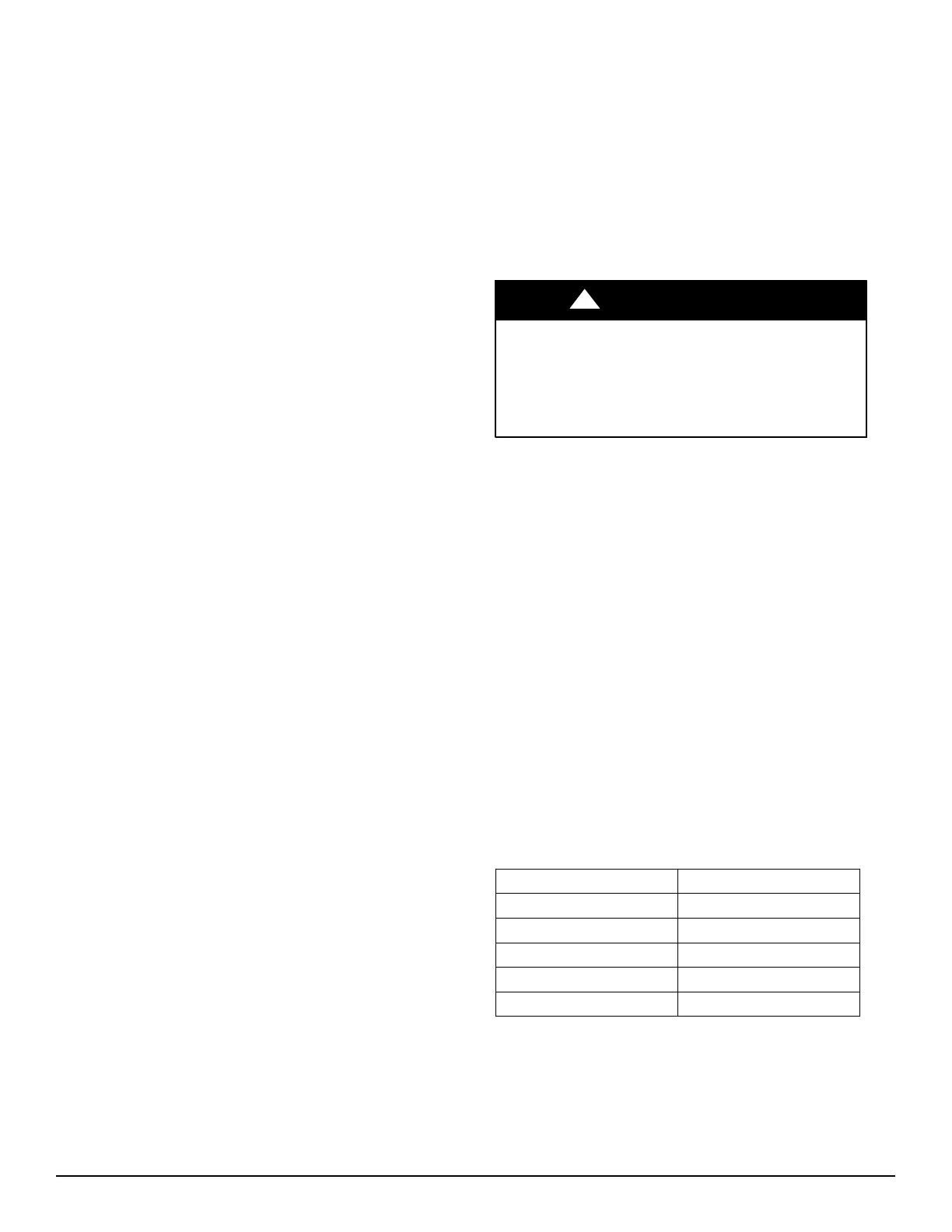
UNIT DAMAGE HAZARD
Failure to follow this caution may result in equipment
damage or improper operation.
Never install suction-- line filter drier in the liquid--line
of a R--410A refrigerant system.
CAUTION
!
6. If requi red, install a 100% activa ted alumina suction
line filter drier at the outdoor unit.
7. Evacuate and charge the system according to the in-
structions in this installation manual.
8. Operate the system for 10 hr. In COOLING MODE
ONLY. Monitor the pressure drop across the suction
line filter drier. If pressure drop exceeds 3 psig
(21kPa), replace suction-line a nd liquid-line filter
driers. Be sure to purge system with dry nitrogen and
evacuate when replacing filter driers. Continue to
monitor the pressure drop across suction-line filter
drier. Repeat filter changes is necessary. Never leave
suction-line filter drier in system longer than 72 hr
(actual time).
Rated Indoor Airflow (cfm)
The table below lists the rated indoor airflow used for the
AHRI efficiency rating for the units covered in this
docume nt.
CHSwithFHS
Model Numbers Full Load Airflow (cfm)
CHS072*A/B --- FHS072 2400
CHS072*G/H --- FHS072 2400
CHS091 --- FHS090 3000
CHS121*A/B --- FHS120 3000
CHS121*G/H --- FhS120 3000