506 01 2303 01 7
Specifications are subject to change without notice.
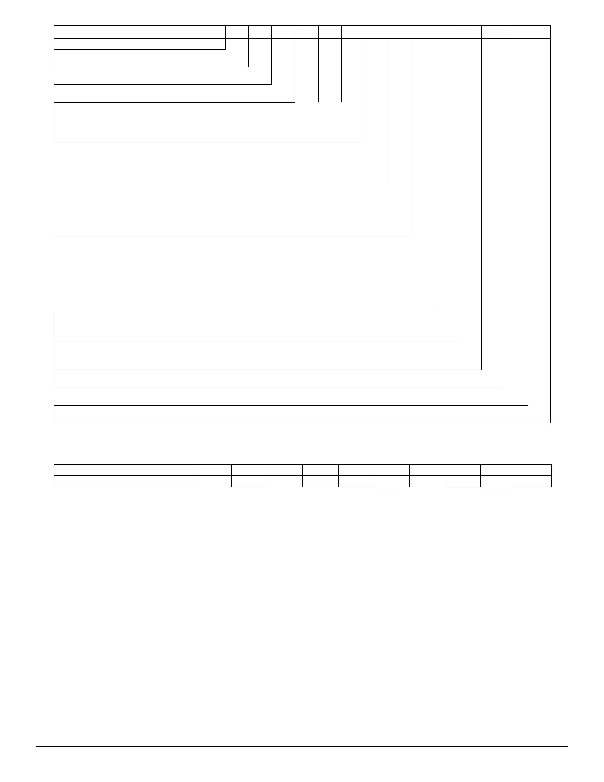
MODEL SERIES CHS0 9 1HGA0A0 0 A
Position Number
12345678910111213
14
Type
Voltage
Refrigerant Options
Coil Options
A = None
C = Non-Fused Disconnect
0 = Electro-Mechanical Controls (standard)
0 = Not Used
Base Unit Controls
A = Cu/Al
B = Precoat Cu/Al
C = E−Coat Cu/Al
M = Cu/Al with Louvered Hail Guards
M = Precoat Cu/Al with Louvered Hail Guards
P = E−Coat Cu/Al with Louvered Hail Guards
Not Used
A = Original Design Sales Code
Efficiency
072 = 6 Tons
091 = 7.5 Tons
121 = 10 Tons
H = 208/230−3−60
L = 460−3−60
S = 575−3−60
0 = None
1 = Un-powered Convenience Outlet
A = Single Circuit
B = Single Circuit with Low Ambient Controller
G = Single Circuit / 2-Stage (072 and 121 units only)
H = Single Circuit / 2-Stage with Low Ambient Controller (072 and 121 units only)
C = R-410A Condensing Unit
H = Heat Pump
S= Standard Efficiency
Nominal Cooling Capacity
Service Options
Electrical Options
C150356
Fig. 2 -- Model Number Nomenclature
DESIGNATESPOSITION
Week of manufacture (fiscal calander)
Manufacturing location5
Sequence number
Year of manufacture (”15” = 2015)
1−2
6−10
3−4
POSITION NUMBER
TYPICAL
12345678910
0515C12345
C150336
Fig. 3 -- Serial Number Nomenclature
.INSTALLATION
Jobsite Survey
Complete the following checks before installation.
1. Consult local building codes and the NEC (Nati onal
Electrical Code) ANSI/NFPA 70 for special installa-
tion requirements.
2. Determine unit location (from project plans) or select
unit locati on.
3. Check for possible overhead obstructions whic h may
interfere with unit lifting or rigging.
Step 1 — Plan for Unit Location
Selec t a location for the unit and its support system (pad,
rails or other) that provides for the m inimum c leara nces
required for safety. This includes the c learance to
combustible surfaces, unit performance and service access
below, around and above unit as specified in unit
drawings. See Fig. 4.
Selec t a unit mounting system that provides adequate
height to allow for removal and disposal of frost and ice
that will form during the hea ting-defrost m ode.
NOTE: Consider also the effect of adjacent units on
airflow performance and control box safety clearance.