12 506 01 2303 01
Specifications are subject to change without notice.
Allow high and low side pressures to equalize. If pressures
do not equalize readily, charge R-410A vapor (using
special service manifold with expansion device) into the
vapor line service port for the low side of system to assure
charge in the evaporator. Refer to GTAC II, Module 5,
Charging, Recover, Recycling, and Reclamation for liquid
charging procedures.
Example:
CHS091
60-ft (18.3 m) linear line length
Equivalent l ine le ngth 90-ft (27.4 m)
Liquid Lift: 20-ft (6.1 m)
Select line sizes from Table 2:
Liquid
1
/
2
in
Vapor 1-
1
/
8
in.
Charge 23.0 lbs (at 75-ft linear l ength)
80% of Operati ng Charge:
0.80 x 23.0 = 17.6 lbs
Factory Shipping Charge: 9 lbs
Field-charge quantity: 17.6 lbs – 9.0 lbs = 8.6 lbs
For linear line l engths longer than 100 ft (30.5 m), contact
your loca l ICP representative for system charge value.
Step 6 — Install Accessories
Accessories requiring modifications t o unit wiring should
be completed now. These accessories may include Winter
Start controls, Low Ambient controls, phase monitor,
Compressor LOCout. Refer to the instructions shipped
with the accessory.
Step 7 — Complete Electrical Connections
ELECTRICAL SHOCK HAZARD
Failure to follow this warning could result in personal
injury or dea th.
Do not use gas pi ping as an electrical ground. Unit
cabi net must have an uninterrupted, unbroken
electrical ground to minimize the possibility of
personal injury if an e lect rical fault should occur. This
ground may c onsist of electrical wire connected to
unit ground lug in control compartment, or conduit
approved for electrical ground when i nstalle d in
accordance with NEC (National Electrical Code);
ANSI/NFPA 70, latest edition (in Canada, Canadian
Electrical Code CSA [Canadian Standards
Association] C22.1), and local electrical codes.
!
WARNING
NOTE: Check all factory and field electrical connections
for tightness. Field-supplied wiring shall conform with the
limitations of minimum 63F(33C) rise.
All units except 208/230-v units are factory wired for the
voltage shown on the nameplate. If the 208/230-v unit is
to be connected to a 208-v power supply, the control
transformer must be rewired by moving the black wire
with the 1/4-in. female spade connector from the 230-v
connec tion and moving it to the 208-v 1/ 4-in. male
terminal on the primary side of the transformer. Refer to
unit label diagram for additional information.
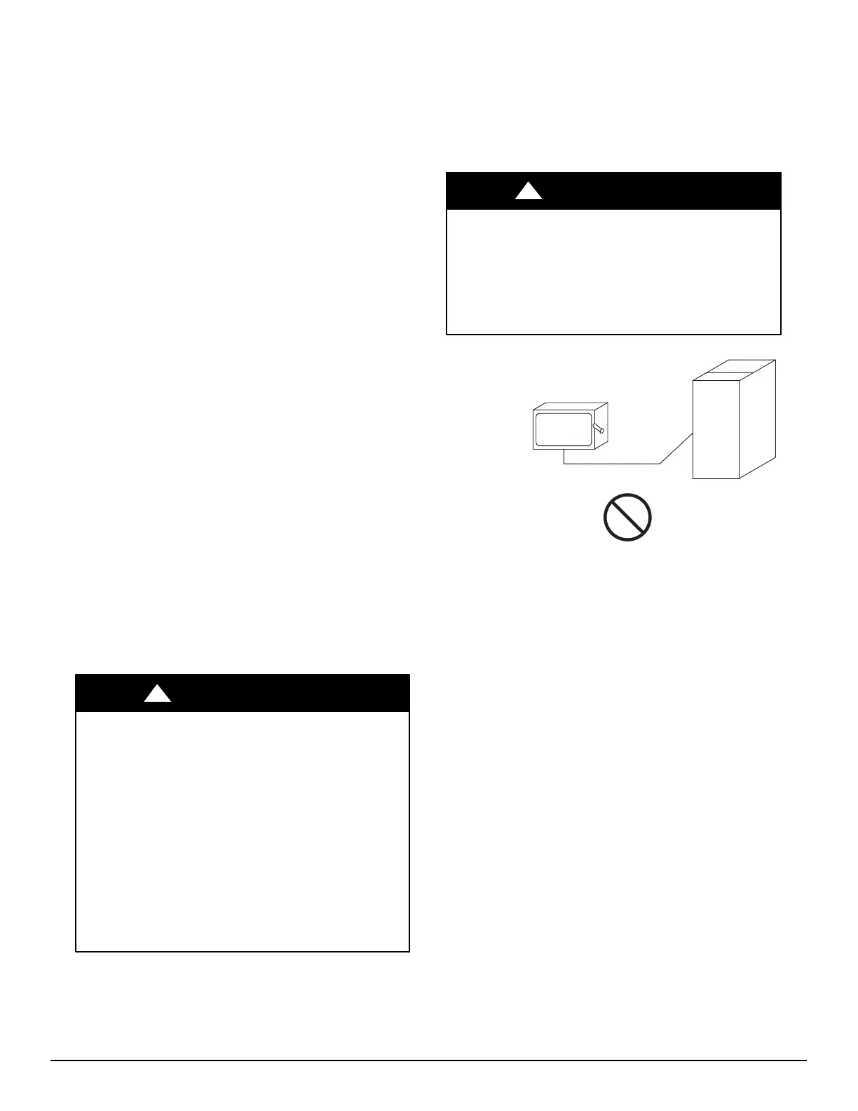
FIRE HAZARD
Failure to follow this warning could result in
intermittent operation or performance satisfaction.
Do not connec t al uminum wire between disconnect
switch and condensing unit. Use only copper wire.
(See Fig. 8.)
!
WARNING
COPPER
WIRE ONLY
ELECTRIC
DISCONNECT
SWITCH
ALUMINUM
WIRE
A93033
Fig. 8 -- Disconnect Switch and Unit
Units Without Factory-Installed Disconnect —
When installing units, provide a disconnect switch per
NEC (National Ele ctrical Code) of adequate size.
Disconnect sizing data is provided on the unit informative
plate. Locate on unit ca binet or within sight of the unit per
national or local codes. Do not cover unit informative
plate if mounting the disconnect on the unit cabinet.
Units with Factory-Installed Disconnect —
The factory-installed option disconnect switch is located
in a weatherproof e nclosure locat ed under the main
control box. The manual switch handle is accessible
through an opening in the access panel.
All Units -
All field wiring must comply with NEC and all local codes.
Size wire bas ed on MCA (Minimu m Circuit Amps ) on the
unit informative plate. See Fig. 9 for power wiring
connections to the unit power terminal block and equipment
ground. Maximum wire size is #4 ga AWG per pole.
Provide a ground-fault and short-circuit over-current
protection device (fuse or breaker) per NEC Article 440
(or local codes). Refer to unit informative data plate for
MOCP (Maximum Over-current Protection) device size.