506 01 2303 01 13
Specifications are subject to change without notice.
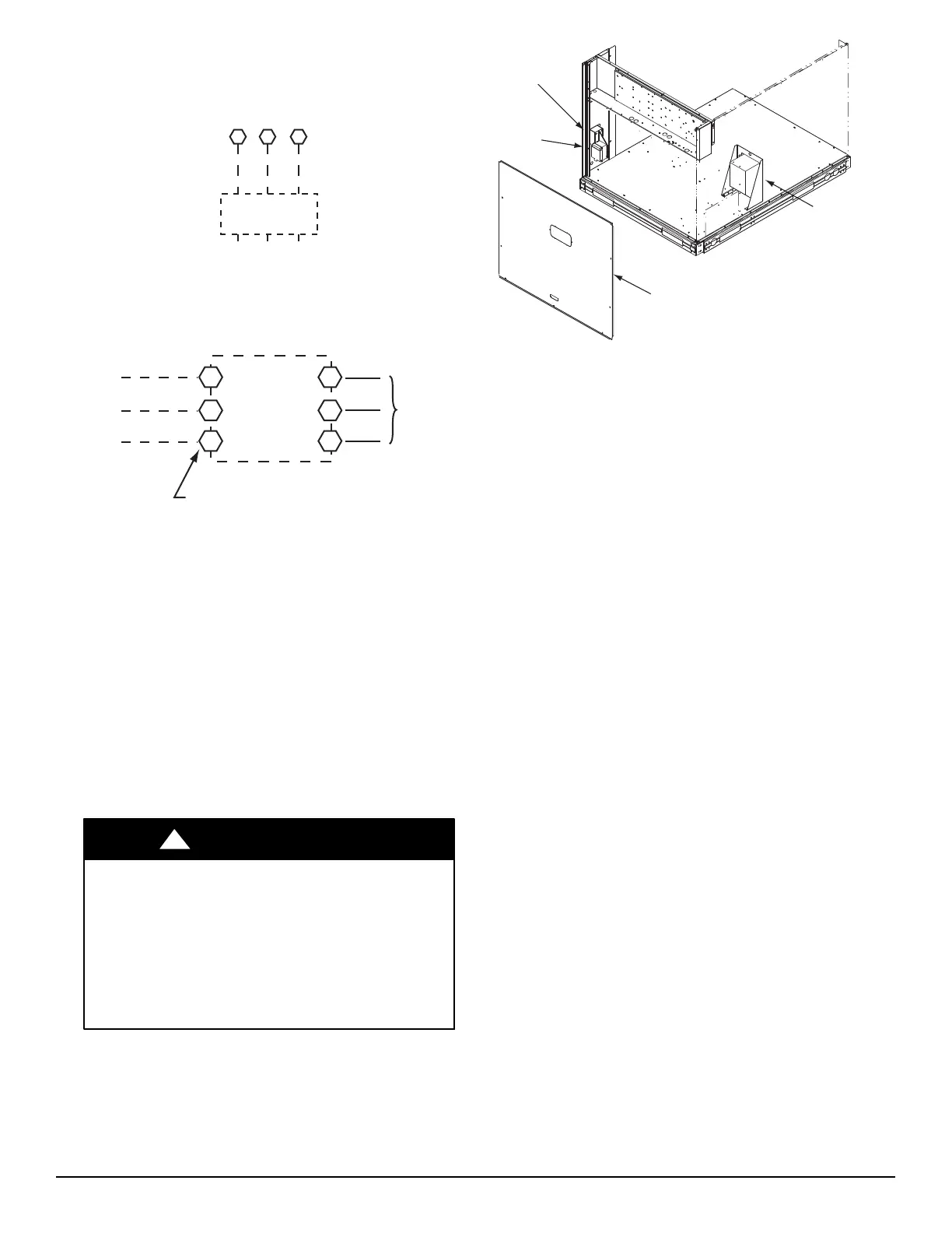
All field wiring must comply with the NEC and local
requirements.
11 13
L1
L2 L3
CTB1
208/230-3-60
460-3-60
575-3-60
Units Without Disconnect Option
Units With Disconnect Option
2
4
6
1
3
5
L1
L2
L3
Optional
Disconnect
Switch
Disconnect factory test leads; discard.
Factory
Wiring
Disconnect
per
NEC
C10204
Fig. 9 -- Power Wiring Connections
Voltage and Current Balance —
Voltage to compressor terminals during operation must be
within voltage range indicated on unit na mepla te. See
Table 8. On 3-phase units, voltages between phases must
be bala nced within 2% and the current within 10%. Use
the formula shown in the legend for Table 8, Note 5 (see
page 15) to determine the percent of volt age imbalance.
Operati on on improper l ine voltage or excessive phase
imbalance constitutes abuse and may cause damage to
electric al components. Such ope ration would invali date
any applicable warranty.
Convenience Outlets
ELECTRICAL OPERATION HAZARD
Failure to follow this warning could result in personal
injury or dea th.
Units with convenience outlet circuits may use
multiple disconnects. Check convenience outlet for
power status before opining unit for service. Locat e it s
disconnec t switch, if a ppropriate, and open it. Tag--out
this switch, if necessary.
!
WARNING
A non-powered convenience outlet is offered on CHS
models. This outlet provides a 125-volt GFCI
(ground-fault circuit-interrupter) duplex receptacle rated
at 15-A behind a hinged waterproof access cover, located
on the e nd panel of the unit. See Fig. 10.
Control Box
Access Panel
Pwd-CO
Transformer
Convenience
Outlet
GFCI
Pwd-CO
Fuse
Switch
C11038
Fig. 10 -- Convenience Outlet Location
Non-powered type: This type requires the field
installation of a general-purpose 125-volt 15-A circuit
powered from a source elsewhere in the building. Observe
national and local codes when selecting wire size, fuse or
breake r require ments and disconnect switch size and
loca tion. Route 125-v power supply conductors into the
bottom of the utility box containing the duplex receptacle.
Installing Weatherproof Cover
A weatherproof while--in--use cover for the factory
installed conveni ence outl ets is now required by UL
standards. This cover cannot be factory mounted due its
depth; it must be installed at unit installation. For
shipment, the convenience outlet is covered with a blank
cover plate.
The wea therproof cover kit is shipped in the unit’s control
box. The kit includes the hinged cover, a backing plate
and gasket.
DISCONNECT ALL POWER TO UNIT AND
CONVENIENCE OUTLET.
Remove the blank cover plate at the convenience outlet;
discard the blank cover.
Loosen the two screws at the GFCI duplex outlet, until
approximately
1
/
2
in (13 mm) under screw heads are
exposed. Press the gasket over the screw he ads. Slip the
backi ng plate over the screw heads at the keyhole slots
and align with the gasket; tighten the two screws until
snug (do not overtighten).
Mount the weatherproof cover to the backing plate as
shown in Fig. 11. Remove two slot fillers in the bottom of
the cover to permit service tool cords to exit the cover.
Check for full closing and latching.