14 506 01 2303 01
Specifications are subject to change without notice.
RECEPTACLE
NOT INCLUDED
COVER – WHILE-IN-USE
WEATHERPROOF
BASE PLATE FOR
GFCI RECEPTACLE
C09022
Fig. 11 -- Weatherproof Cove r Installation
Field Control Wiring —
CHS unit control voltage is 24 v. See Figs. 20 -- 22 for
typical fiel d control connec tions a nd the unit’s label
diagram for field-supplied wiring details. Route control
wires to the CHS unit through the opening in unit’s e nd
panel to the connections terminal board in the unit’s
control box.
The CHS unit requires an external temperature control
device. This device can be a thermostat (field-supplied)).
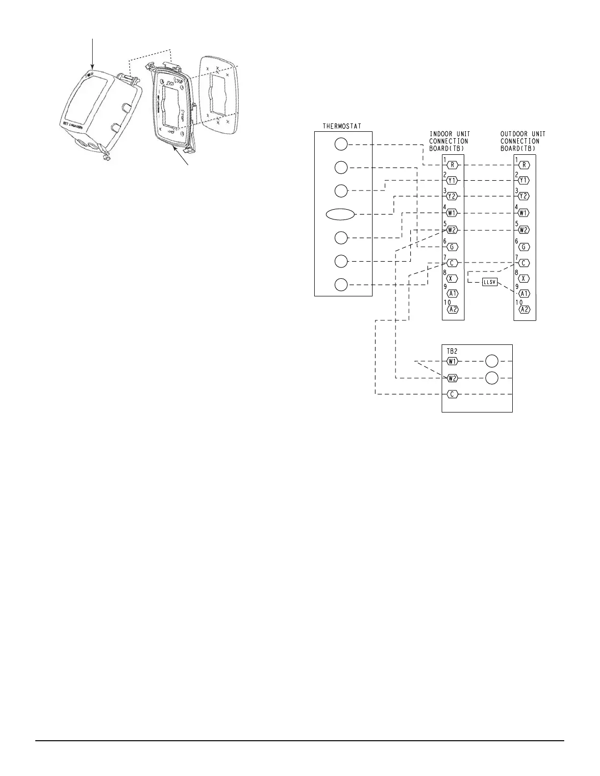
Thermostat —
Install an approved accessory thermostat according to
installation instructions included with the accessory. For
complete economizer function, select a two—stage
cooling thermostat. CHS****G/H units requi re a
two--stage thermostat.
CHS unit control system requi res a conventional electric
thermostat that will energize the G terminal on a call for
Cool and Heat mode. Do not configure the thermostat a a
heat pump type; Heat mode will not work with a
thermostat configured for heat pump.
Locate the thermostat accessory on a solid wall in the
conditioned space to sense average tempera ture in
accordance with the thermostat installation instructions.
If the thermostat contains a logi c circuit requiring 24-v
power, use a thermostat cable or equivalent single leads of
different colors with minimum of five leads between the
CHS unit’s outdoor unit connection board and the indoor
unit connecti on board. If the thermostat does not require a
24-v source (no “C” connection required), use a
thermostat cable or equivalent with minimum of four
leads. One addit ional lead is re quired between the indoor
unit connection board and the thermostat for terminal G.
If the accessory electric heat is used, one additional wire
is require d between the indoor unit connection board and
the thermostat for terminal W2. Check the thermostat
installation instructions for additional features which
might require a dditiona l conductors in the cable.
NOTE: Two--stage units require an additional wire for
the Y2 conne ction.
For wire runs up to 50 ft. (15 m), use no. 18 AWG
(American Wire Gage) insulated wire (35C minimum).
For50to75ft.(15to23m),useno.16AWGinsulated
wire (35C minimum). For over 75 ft. (23 m), use no. 14
AWG insulated wire (35C minimum). All wire sizes
larger than no. 18 AWG cannot be dire ctly connected to
the t hermostat and will require a junc tion box and splice
at the thermostat.
R
Y1
G
O/B/Y2
C
W2
W1
H1
H2
HEAT PUMP INDOOR UNIT
ELECTRIC HEATER
HEAT PUMP INDOOR UNIT
WITH ELECTRIC HEATER -
THERMOSTAT CONNECTIONS
NOTE: Y2 connection for two stage units only
(See NOTE)
C150420
Fig. 12 -- Typical Remote Thermostat Connections
Step 8 — Wind Baffles for Low Ambient Control
CHS****B and CHS****H units includes the factory
installed 32 LT Motor mas ter Low Ambien t Contr ol.
Units with 32LT Motormaster control require the addition
of wind baffles to ensure full range low ambient
operation. Mate rial data and dimensions for wind baffles
are included in t he Appendix C section, Low Ambient
Control, starting on page 46. Fabricate the wind baffles
and mount per instructions.